307-847 31
Removing
and Installing the Pump
WARNING
To
reduce the risk of
serious injury
, including fluid in
-
jection
always follow the
Pressure Relief Procedure
Warning on page 14 before checking, adjusting,
cleaning or shutting off the sprayer.
Disconnect the
spark
plug!
Removing the pump See
Fig. 26.
1.
Flush the pump. Relieve pressure. See page 14.
2. Hold the intake valve (423) with a wrench and un-
screw
the suction tube (30). Remove the hose
(59).
For upright carts, remove the spring clips (112,114)
and
drain hose (1
13).
3.
Push the retaining spring (26) up. Push the pin (25)
out the rear
.
4. Loosen
the locknut (27). Unscrew the pump. See be
-
low
for how to repair the pump.
Fig. 26
0477
59
26
25
27
112
113
114
30
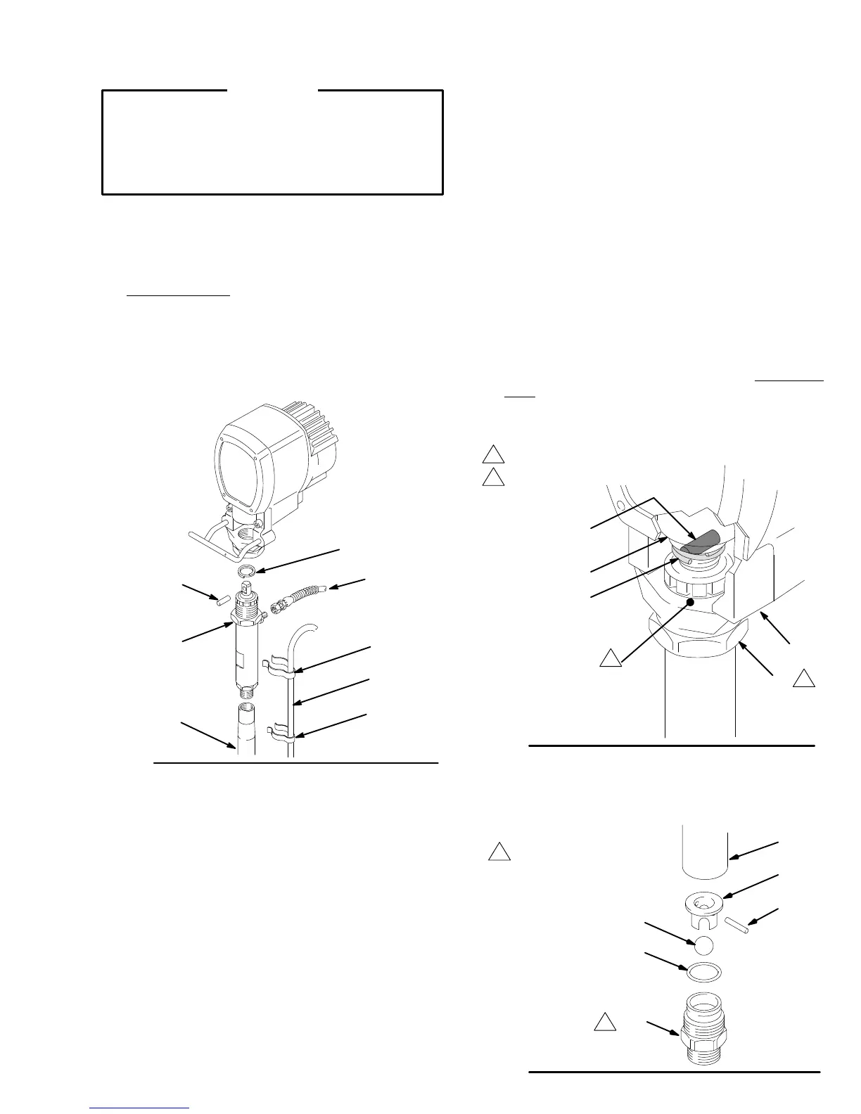
Installing the pump See
Fig. 27.
1. Screw
the
pump about 3/4 of the way into the bearing
housing
(21). Hold the pin (25) up to the pin hole on
the
connecting rod (22) and continue screwing in
the
pump
until the pin slides easily into the hole.
2.
Back of
f the pump until the top threads of the pump
cylinder
are flush with the
face of the bearing housing
and
the outlet nipple faces back.
3. Push
the retaining spring (26)
into the groove all the
way around the connecting rod. Tighten the locknut
(27)
to 90 ft–lb (1
10 N.m) using a 2 1/4 in. open end
wrench
and a light hammer
.
4. Install
the
front cover and screws. Connect the pump
outlet
hose. Install the suction tube parts. For Upright
carts,
install the spring clips and drain hose.
Fig. 27
0031
21
26
22
25
27
1
2
Face
of bearing housing
T
orque to 90 ft–lb (1
10 N.m)
1
2
Displacement
Pump Repair
Disassembly procedure
1. Remove
the pump from the sprayer
. See above.
2.
Disassemble the intake valve. See Fig. 28.
3. Clean and inspect the parts. Replace any worn or
damaged parts. Use a new o–ring (401* ). If no fur-
ther sevice is needed, reassemble the intake valve
and
torque
it into the cylinder to 1
10 ft–lb (146 N.m).
Fig.
28
*401
421*
423
419
420
*404
1
Torque
to
1
10 ft–lb
(146 N.m)
1