Pressure
Control Adjustment
WARNING
USE
EXTREME CAUTION WHEN PERFORMING THIS CALIBRA
TION PROCEDURE to reduce the risk of a
fluid injection injury or other serious injury
, which can result from component rupture, electric shock, fire, explo
-
sion or moving parts.
This procedure sets the sprayer to 2600–3000 psi
(182–210
bar) MAXIMUM WORKING PRESSURE.
This
procedure must be performed when the pressure
control assembly is removed and reinstalled, or re-
placed,
to be sure the sprayer is properly calibrated.
Improper calibration can cause the sprayer to over–
pressurize
and result in component rupture, fire or
ex
-
plosion.
It may also prevent the sprayer from
obtaining
the maximum working pressure, resulting in poor
sprayer
performance.
NEVER
attempt
to increase the fluid outlet pressure by
performing these calibrations in any other way.
NEVER EXCEED 3000 psi (210 bar) MAXIMUM
WORKING PRESSURE. Normal operation of the
sprayer
at higher pressures could result in component
rupture,
fire or explosion.
ALWAYS
use a
new
50 foot (15.2 m) spray hose, rated
for at least 3000 psi (210 bar) MAXIMUM WORKING
PRESSURE,
when performing this procedure. A
used,
under–rated hose could develop a high pressure leak
or rupture.
AVOID touching the wires in the pressure control as-
sembly when the control box cover is removed, to re-
duce
the risk of electric shock.
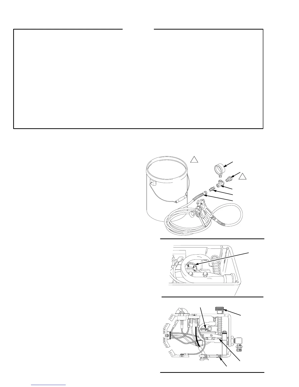
Service Tools Needed
NEW
50 foot (15.2 m), 3000 psi (210 bar), flexible nylon,
airless spray hose, p/n 223–541
0–5000 psi (0–350 bar) fluid–filled pressure gauge, p/n
102–814
NEW
spray tip, size 0.025 to 0.029
3/8 in. ignition wrench or nut driver
5 gallon pail and water or mineral spirits
Swivel, p/n 156–823
Nipple, p/n 162–453
T
ee, p/n 104–984
Set Up
1. Follow
the
Pressure Relief Procedure W
arning
on
page
14.
2.
Set up the system as shown in Fig. 23.
Set the Dead Band (Pressure Differential)
NOTE: Do not alter this adjustment if the wheel is al-
ready
set as shown in Fig. 24.
1.
Remove the pressure control cover
.
2. Set the white differential wheel (A) on the micros-
witch.
T
urn the wheel so the letter
F
is concealed be
-
hind
the switch and the letter
A
is the
first letter seen.
Pressure Up
1. Start
the sprayer and prime it.
2.
Adjust the pressure to 2600 psi (180 bar).
3. Shut off the engine. If the pressure drops, replace
pump
packings before proceeding. See page 31.
Adjust the Pressure See
Fig. 25.
1.
Remove the pressure control plug (326).
2. Turn and hold the pressure control knob (B) at the
maximum
pressure setting.
3. Engage
the nut (C): insert the nut driver through the
pressure
control
hole, or use the ignition wrench from
the
front of the pressure control.
a. Loosen
the nut just until you hear a click. ST
OP.
b. Slowly tighten the nut just until another click is
heard.
ST
OP.
4.
Replace the plug (326) and pressure control cover
.
Fig. 23
0474
102–814
156–823
104–984
162–453
223–541
Connect
to
fluid outlet
Fig.
24
0475
A
h
Fig. 25
A
B
326
C
0151