Pressure
Control Replacement
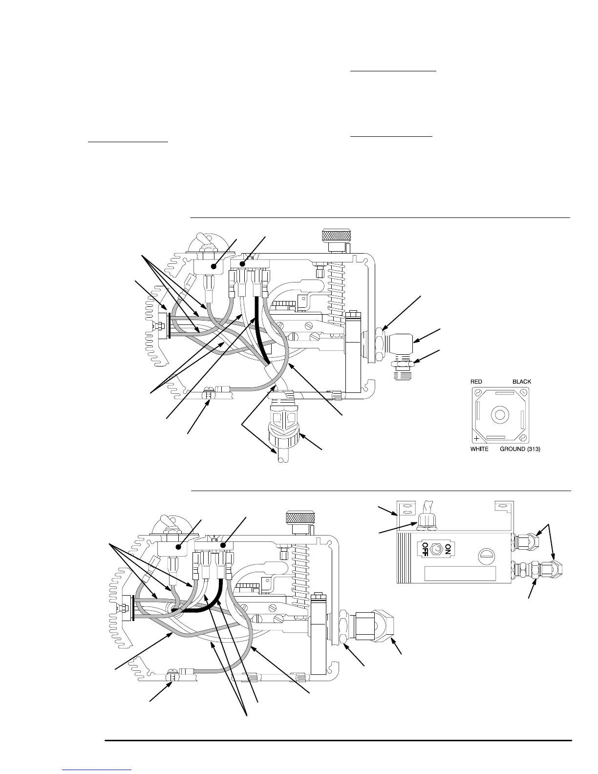
5. Disconnect the black, red and white wires from the
rectifier
(307) and switch (302),
which are sheathed
with
the conductor (314). See Fig. 22.
6. Unscrew
the connector (318 or 108) from the control
box,
pulling the conductor and wires out with it.
7. For
the upright
cart
, remove the nipple (316) from the
elbow
(317). See Fig. 22.
8. Use a wrench to hold the hex of the adapters (A)
while
removing the elbows (317, or 320 and 319).
9.
Reassemble in the reverse order
.
10. For
the upright carts
, guide the new pressure control
wires
through the wire clamps (97).
Fasten the wire
-
clamps to the cart with the same screws, lock-
washers,
and nuts (61, 9, 62) which hold the bracket
(76)
to the cart. See Fig. 20.
11. For
the lo-boy carts
, guide the pressure control wires
through the single wire clamp (97), and install the
screws
and washers (62, 9) to hold the bracket (107)
to
the cart. See Fig. 20.
12. Perform the Pressure Control Adjustment on
page
30 before regular operation of the sprayer
.
Rectifier
(307) connections
316
h
317
RED
BLACK
WHITE
315,305
318
For
Lo-Boy cart sprayers
For Upright cart sprayers
BLACK
WHITE
Ref 320
315,305
RED
Top
view
A
RED
GROUND
GROUND
108
107
320
319
Fig.
22
RED
RED
307
307
313
314
313
0151
0148
0150
0165
RED
A
302
302