Displacement
Pump Repair
Fig.
31
424
Do
not allow nut (41
1) to
move when installing piston
onto rod
1
2
T
orque nut
against rod to
19 ft–lb (26 N.m)
2
411
1 2
6. Use a wrench to CAREFULLY tighten the nut (411)
against
the piston rod to 19 ft–lbs (26 N.m). See Fig.
31.
NOTE: Use two wrenches to maintain the alignment
mentioned
in the NOTE following Step 4, page 32.
7. Put
a new o–ring (417*) firmly in the cylinder groove.
See
Fig. 33.
8. One
at a time stack the male
gland (408*), alternate
the
packings (413*,407*), and then
install the female
gland (409*), into the top of the cylinder (419). See
Fig.
33.
9. Install
the packing
nut (416) and plug (405), but leave
loose
for now
. See Fig. 33.
NOTE: The
tapered end of the sleeve is the bottom of
it.
Do
not install it upside down. See Fig. 32.
10. Coat the piston rod and packings with oil. Carefully
slide the assembly (A) INTO THE TOP OF THE
SLEEVE
(418)
. Then slide the sleeve/piston rod
as
-
sembly INTO THE BOTTOM OF THE CYLINDER
(419). This procedure helps prevent damaging the
packings
during reassembly
. See Fig. 32.
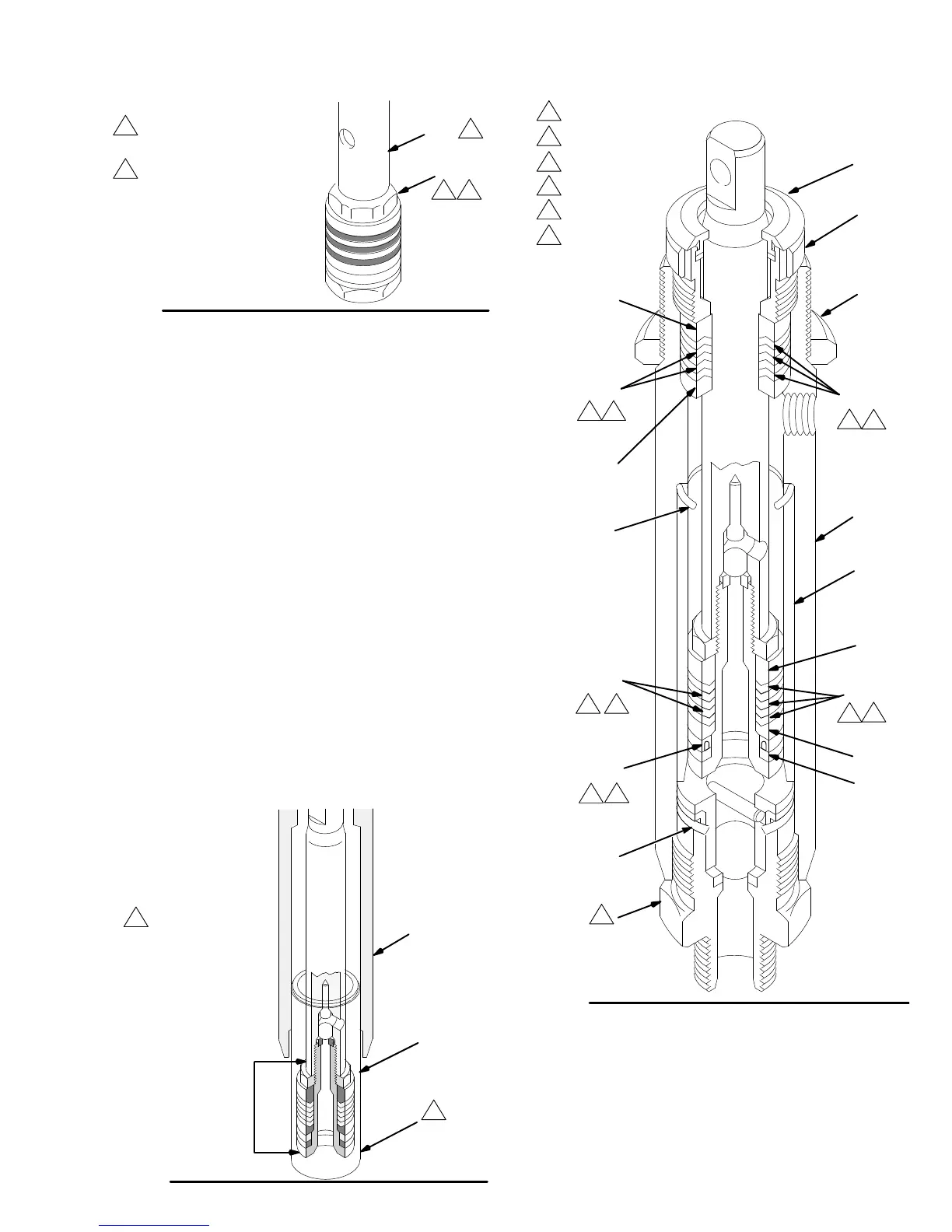
Fig. 32
0030
419
418
A
1
Tapered
end
1
419
Fig.
33
412*
413*
410*
405
*406
*403
415*
414*
*401
*408
*407
*409
*417
418
416
27
1
3
4
2
Leather
Polyethylene
Lips
must face DOWN
Lips must face UP
U–cup seal
T
orque to
1
10 ft–lb
(146 N.m)
1 3
3
2
1 4
2
4
5
6
3
5
6
11. Screw
down the cylinder locknut (27) until
it is finger
tight
at the bottom of the external cylinder threads.
12. Put
the flats
of the intake valve (423) in a vise. Install
a new o-ring (401*) and screw the intake valve into
the pump cylinder. See Fig. 33. Torque the valve to
110
ft–lb (146 N.m).
13.
Reinstall the pump. See page 31.