R
robertvanceSep 12, 2025
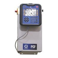
Why is my Graco PR70 Dispenser display module completely dark?
- AAnn JenkinsSep 12, 2025
If the display module on your Graco Dispenser is completely dark, it could be due to: * No power: Verify that the rear AC power switch is ON. * A blown fuse: Replace the machine fuses. * A loose connection: Tighten the 5-pin cable on the Display Module. * A bad display module: Replace the Display Module.