2.5 Vertical system
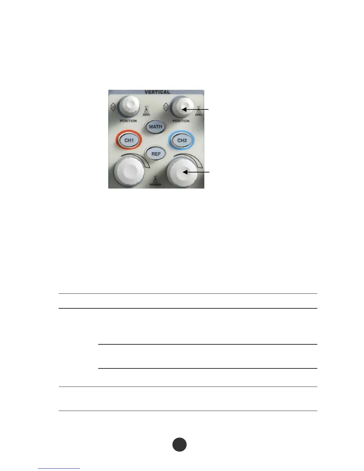
As shown in figure 2-5 below, a series of keys and knobs are in the vertical control
region (VERTICAL).
Vertical POSITION knob
Volt/div knob
Figur
e 2-5 Vertical knobs
As seen in the figure above, each channel has individual vertical menu key and knob for
regulating the vertical gear and offset. Moreover, the waveform display of the
corresponding channel can be started or stopped by pressing [CH1] or [CH2].
2.5.1 Channels CH1 and CH2
Table 2-3 Function menu 1 of CH1 and CH2:
Option setup Description
DC
Not only pass through the AC component of the input
signal but also pass through the DC component of the
input signal.
AC
Reject DC component of the input signal and an AC
signal lower than 10Hz.
Coupling
GND Cut off the input signal.
RUN Limit the bandwidth to 20MHz, and reduce the noise. Bandwidth
limit
STOP
14