Set the waveform brightness:
Press “Wave brightness”, and revolve the [UNIVERSAL] knob to regulate the display
brightness of the waveform.
Set the grid brightness:
Press “Grid brightness”, and revolve the [UNIVERSAL] knob to regulate the display
brightness of the grid.
Set the display format:
Press “ Next Page1/2” to skip to page 2 of the display menu. Press “Format” to select
“YT” or “XY”.
Set the screen:
Press “Screen” to select “Normal” or “Inverse” to set the color of the screen.
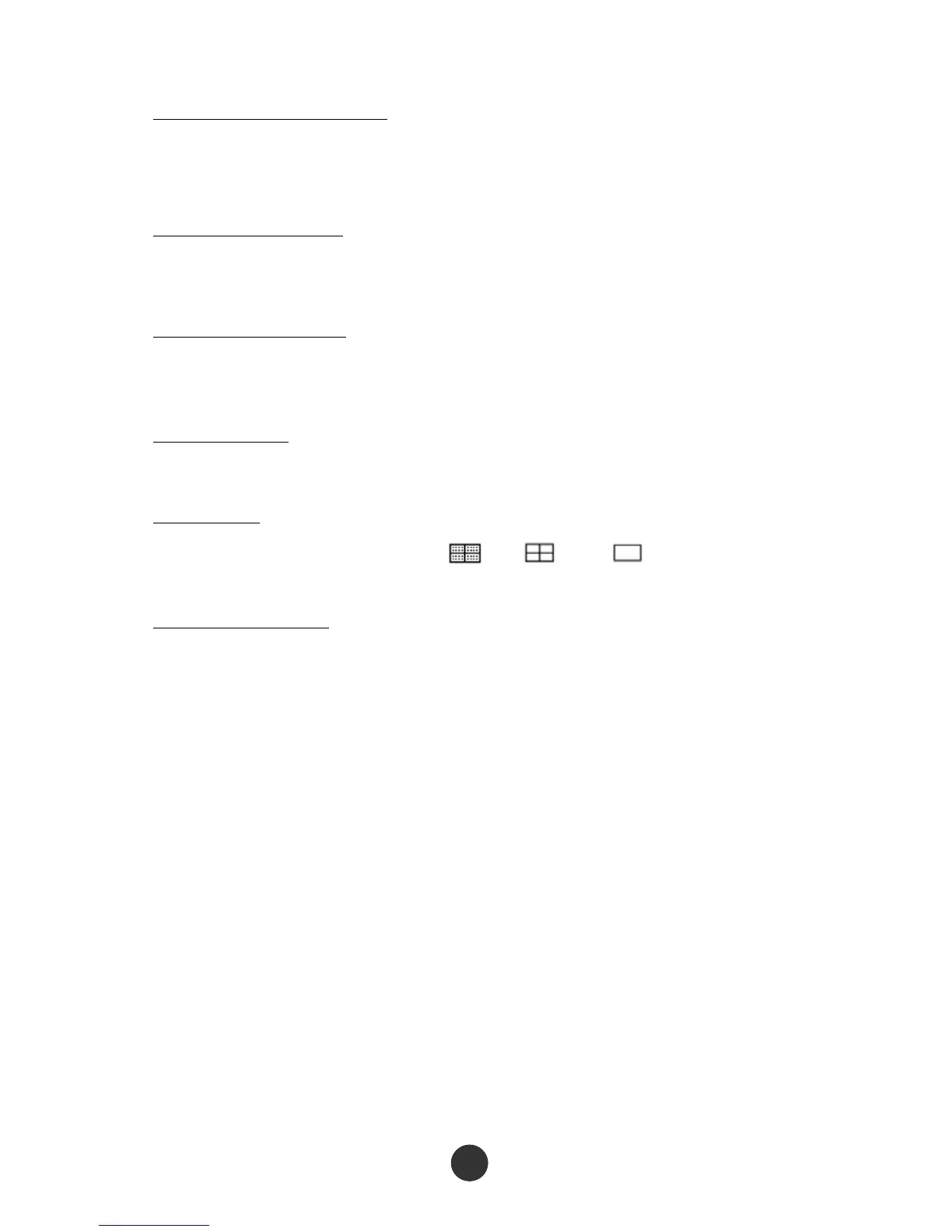
Set the grid:
Press the “Grid” option key to select “ ”, “ ” or “ ” to set whether the
grid is displayed on the screen.
Set the menu display:
Press the “Menu display” option key to select “2s”, “5s”, “10s”, “20s” or “Infinite” to
set the maintained display time length of the menu on the screen.
2.9.1 X-Y mode
Use the XY format to analyze phase difference. At the format, the voltage of channel 1
determines coordinate X (horizontal) of a point, while the voltage of channel 2
determines coordinate Y (vertical) of the point. The oscilloscope uses a non-triggered
sampling mode to display the data as a spot. Figure 2-48 shows the YT mode, and it
shows that signals of the two channels have the same amplitude and frequency and
the phase difference is 90 degrees. After switching to X-Y mode, the waveform is
shown in figure 2-49 below.