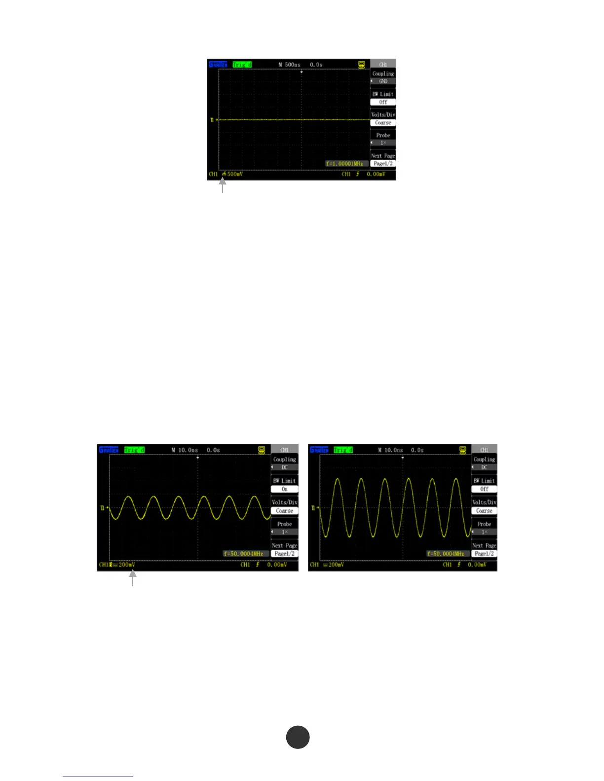
Figure 2-8 Set GND
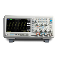
2. Setup of channel bandwidth limit
Using Channel CH1 as an example, the measured signal is a pulse signal with
high-frequency oscillation:
Press [CH1]→“Bandwidth limit”→“On”, and set the bandwidth limit as ON state.
The amplitude of the high-frequency component higher than 20MHz contained in
the measured signal is limited, as shown in figure 2-9.
Press [CH1]→“Bandwidth limit”→“OFF”, and set the bandwidth limit as OFF state.
The amplitude of the high-frequency component contained in the measured
signal is unlimited, as shown in figure 2-10.
Figure 2-9 Bandwidth limit ON Figure 2-10Bandwidth limit off
3. Regulation and setup of gear
Vertical gear regulation comprises two modes, including coarse tuning and fine tuning,
and the vertical gear range is 2mV/div ~ 5V/div when the probe is set as 1X .
Use CH1 as an example:
GND identification
Bandwidth limit identification