points cannot be acquired at the mode, which may cause “fake wave phenomenon”
and may miss spike pulses, so “peak value detection” mode should be adopted
under these conditions.
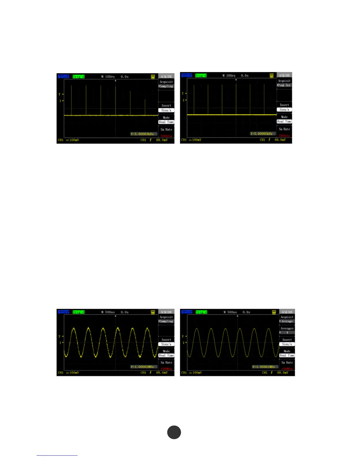
Figure 2-38 Sampling mode Figure 2-39 Peak value detection mode
■ Peak value detection: The oscilloscope finds out the maximal value and the minimal
value of the input signal in each sampling interval and uses these values to display
the waveform.
Advantage: Spike pulses that may be missed can be acquired and displayed and
signal confusion can be avoided at the mode.
Shortcoming: Loud noise is displayed at the mode.
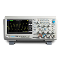
■ Average value: The oscilloscope acquires a plurality of waveforms and displays the
final waveforms after averaging the waveforms.
Advantage: Random or unrelated noises in the displayed signal can be reduced at
the mode. The signal shown in figure 2-40 has loud noises, while the signal shown in
figure 2-41 adopts the average mode, so the noises are greatly reduced. What calls
for attention is that: the higher the average time is, the better the waveform quality is,
but the slower the refreshing speeds of the waveform is.
Figure 2-40 Sampling mode Figure 2-41 Average mode
■ Real-time sampling: The real-time sampling mode realizes suffusion of the storage
space during each sampling. The real-time sampling rate is at most 1GSa/s.