Maintenance
Replacement Procedures
8-50
(Revised 1/02)
Boiler Heating Element (Electric units Only)
Installation
(
continued)
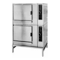
CC20-E
4. Connect heater element wires to the terminal block.
5. Install boiler cover, and the right side and center racks.
WARNING
When oven power is turned on, there is high voltage present
in the electrical components compartment.
6. Connect oven to the branch circuit, and operate oven in Steam mode with
timer running.
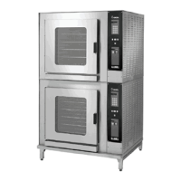
CC10-E
7. Using a clamp-on ammeter, measure current flow in one of the wires for each
wire pair B6-B5 (BH1), B4-B3 (BH2), and B1-B2 (BH3). Current reading
should be approximately 14.5 amps for the 208V unit and 13.0 amps for the
240V unit.
CC20-E
7. Using a clamp-on ammeter, measure current flow in one of the wires for each
wire pair B1-B2 (BH1), B3-B4 (BH2), and B5-B6 (BH3). Current reading
should be approximately 33.7 amps for the 208V unit, 29.2 amps for the 240V
unit, and 14.6 amps for the 480V unit.
8. Install right side cover.