Description components12
Date of issue: October 2011
Automatic Greasing System OnePlus
EG1605R01
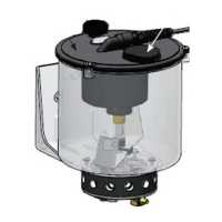
2.5 The plunger pump
The electric motor drives the plunger pump through a reduction gear. The plunger
pump comprises a drive shaft with excentric, a cylinder with piston, and a non-
return valve. The excentric moves the piston back and forth, once every revolution
of the drive shaft. During the return stroke of the piston, grease is sucked from the
reservoir into the cylinder (through an opening in the cylinder wall). During the
forward stroke of the piston, the grease is pressed, via the non-return valve,
towards the output port of the pump unit. The amount of grease supplied during
each stroke (revolutions of the drive shaft) depends on the (fixed) diameter of the
cylinder and the stroke length of the piston.
2.6 Safety and control features
2.6.1 Maximum grease pressure
A relief valve is installed in the grease channel between the plunger pump and the
grease output port. This relief valve will start to lead the grease back to the
reservoir if the maximum grease pressure is exceeded during the pump phase of a
greasing cycle. The grease pressure may become too high, for example, when one
of the grease lines to the grease points has become blocked, or when the viscosity
of the grease has become too high (at low temperature).
2.6.2 Defective wiring and short-circuits
Open-loads (interruptions) and short circuits in the pump wiring will be detected
and processed by the control unit.
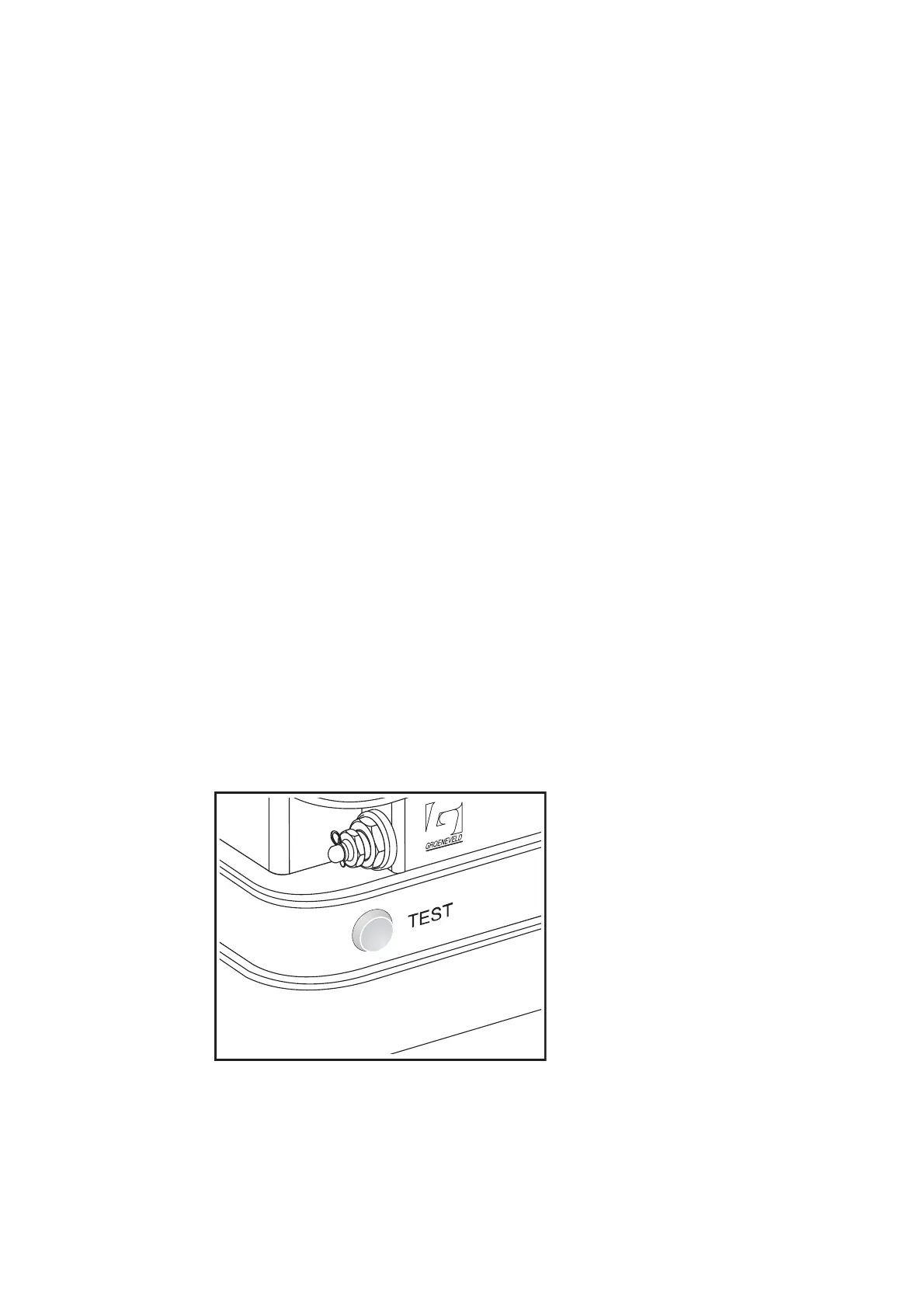
2.7 The test push button
The test push button on the pump unit has two functions:
• Performing a test cycle via the grease output port of the pump unit.
• Retrieving error messages stored in the memory of the control unit.
Figure 2.4 The test push button