Installation32
Date of issue: October 2011
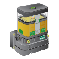
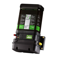
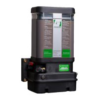
Automatic Greasing System OnePlus
EG1605R01
4.7.2 Mounting the secondary lines
Take attention at the following points during mounting the secondary grease lines
and couplings:
• Always make sure the screw threads of the coupling(s) and the grease point
are identical.
• To identify them, elbow couplings with metric screw thread are marked with
a “M”. Straight couplings with metric screw thread have a groove on their
hexagons.
• Always apply brake booster rubbers when routing grease lines along the
vehicle’s booster lines (this to prevent the booster lines from becoming
pinched-off (over time) by the tie-wraps that are usually used to fix grease
lines).
• Never add extra grease points on your own accord. The integrity of certain
structures may be adversely affected by drilling holes. Always adhere to the
relevant directives issued by the vehicle’s manufacturer.
If a vehicle-specific greasing plan is available, the types (or combination) of cou-
plings to be used at grease point will have been noted on that plan.
First remove the existing grease nipple at the grease point, and replace it by the
required coupling(s).
If the grease point to be connected is a so-called “added” grease point, a hole must
be drilled and the right thread tapped. Do not forget to clean the new hole of any
debris. Mount the required coupling(s) onto the grease point (see the greasing
plan). Make sure that elbow couplings point in the direction of the grease line
(avoid unnecessary (sharp) corners in the grease line).
ATTENTION:
Always check that the newly drilled grease point is open by applying a
hand-operated grease gun to it.
1. Determine the most suitable route for the (composite) grease line to the
grease line(s).
2. Cut the grease line at roughly the required length.
3. Determine approximately, the required length of the individual grease lines
in a composite (polyamide) line. Make absolutely sure that you do not dam-
age the individual grease lines!
4. Strip and remove the outer jacket.
5. Fix the line in place with tie-wraps or clamps up to the coupling at the grease
point.
6. Cut the (individual) grease line to its required length and connect it with the
coupling to the grease point.