English (GB)
24
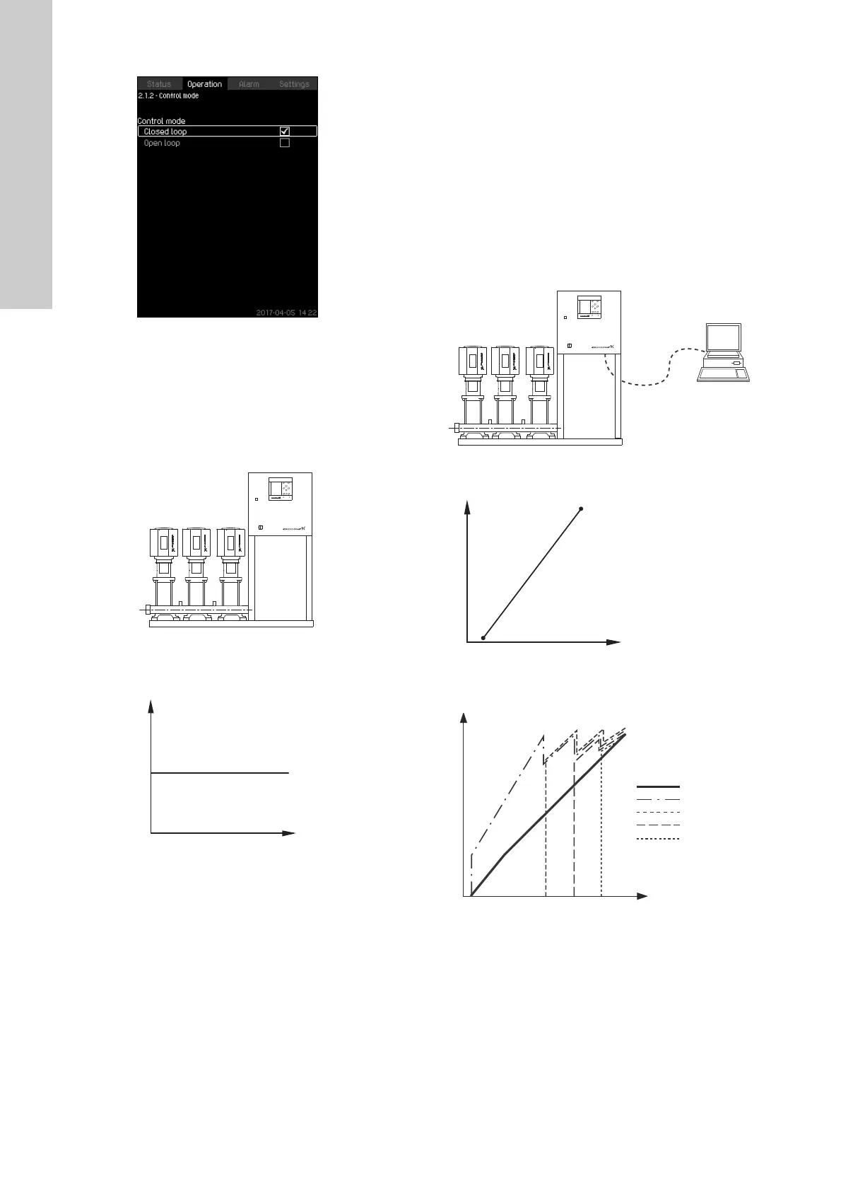
8.5.3 Control mode (2.1.2)
Fig. 19 Control mode
Description
There are two control modes, namely closed and open loop.
Closed loop
The typical control mode is "Closed loop" where the built-in PI
controller ensures that the system reaches and maintains the
selected setpoint. The performance is based on the setpoint set
for closed loop. See figs 20 and 21.
Fig. 20 Booster system controlled by built-in PI controller
(closed loop)
Fig. 21 Regulation curve for closed loop
Setting via the operating panel
• Operation > Further settings > Control mode > Closed loop.
Set the setpoint. See sections 8.5.4 Alternative setpoints (2.1.3)
and 8.5.1 Operation (2).
Open loop
In open-loop control mode, the pumps run at a fixed speed. The
pump speed is calculated from the performance set by the user
(0-100 %). The pump performance in percentage is proportional
with the flow rate.
Open-loop control mode is usually used when the system is
controlled by an external controller which controls the
performance via an external signal. The external controller could
for instance be a building management system connected to the
MPC system. In such cases MPC is like an actuator. See figs 22
and 23.
Fig. 22 Booster system with external controller (open loop)
Fig. 23 Regulation curve for open loop
Fig. 24 Regulation curve for MPC-E system in open loop
TM03 2231 3905TM03 2390 4105
TM03 2232 3905TM03 2391 3607TM03 9977 4807
Input [%] from external
controller
Flow rate [m
3
/h]
Flow rate [m
3
/h]
Input [%] from
external controller
Pump 1
Pump 4
Pump 3
Flow rate
Pump 2

 Loading...
