English (GB)
19
8.3 Description of functions
The description of functions is based on the four main menus of
the CU 352 control unit:
•Status
• Operation
•Alarm
•Settings.
The functions apply to all control variants unless otherwise
stated.
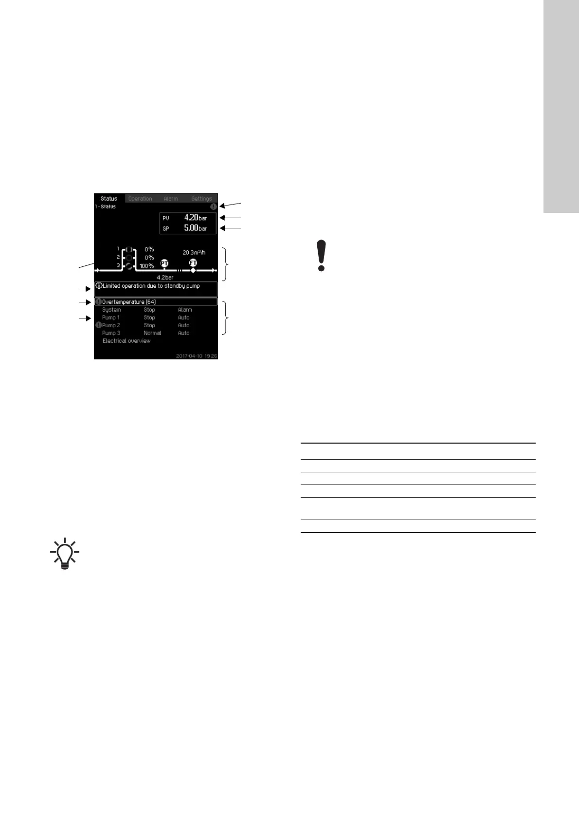
8.4 Status (1)
This display is shown when the power is switched on, and it
appears if the buttons of the operating panel remain untouched
for 15 minutes.
Fig. 6 Status
Description
No settings can be made in this menu.
The actual value (process value, PV) of the control parameter,
usually the outlet pressure, is shown in the upper right corner (G)
together with the selected setpoint (SP) (H).
The upper half of the display (A) shows a graphic illustration of
the pump system. The selected measuring parameters are shown
with sensor symbol and actual value.
In MPC-E systems where the differential pressure across the
pumps and pump curve data are known, the display shows the
estimated flow rate when the flow rate and speed of the pumps
are within a range where it is possible to estimate the flow rate.
In the middle of the display, an information field (I) is shown if any
of the following events occurs:
• Limited operation due to standby pump
• Proportional-pressure influence active
• External setpoint influence active
• Alternative setpoint active
• Low flow boost active
• Pressure relief active
• Clock program active
• Remote-controlled via GENI (RS-485)
• Limited due to reduced operation
• Stopped due to low flow.
The lower display half (B) shows the following:
• the most recent active alarm, if any, and the fault cause with
the fault code in brackets
• system status with actual operating mode and control source
• pump status with actual operating mode.
If the fault is related to one of the pumps, a warning or alarm
symbol is also shown in front of the status line (D) of the pump in
question. At the same time, the pump status indicator (E)
changes colour to either yellow or red as described in the table
below. The warning or alarm symbol is shown to the right in the
top line of the display (F). As long as a fault is present, this
symbol is shown in the top line of all displays.
To open a menu line, select the line with [Down] or [Up] and press
[OK].
The display allows you to open status displays showing the
following:
• actual alarms
• system status
• status of each pump.
Description of pump status
≈ : This indicates that the flow rate is an estimated value.
The estimated flow rate may differ from a measured
value.
If a fault has occurred, the warning symbol or alarm
symbol is shown in the line (C) together with the
cause and fault code, for instance "Overtemperature
(64)".
Pump status indicator Description
Rotating, green The pump is running.
Permanently green The pump is ready (not running).
Rotating, yellow Warning. The pump is running.
Permanently yellow
Warning. The pump is ready (not
running).
Permanently red Alarm. The pump is stopped.

 Loading...
