Arabic (AR)
513
4. Settings
ﺔﺣﻔﺻﻟﺍ ﻥﻣ ﻊﺑﺗ
ُ
ﻳ461
1 ->
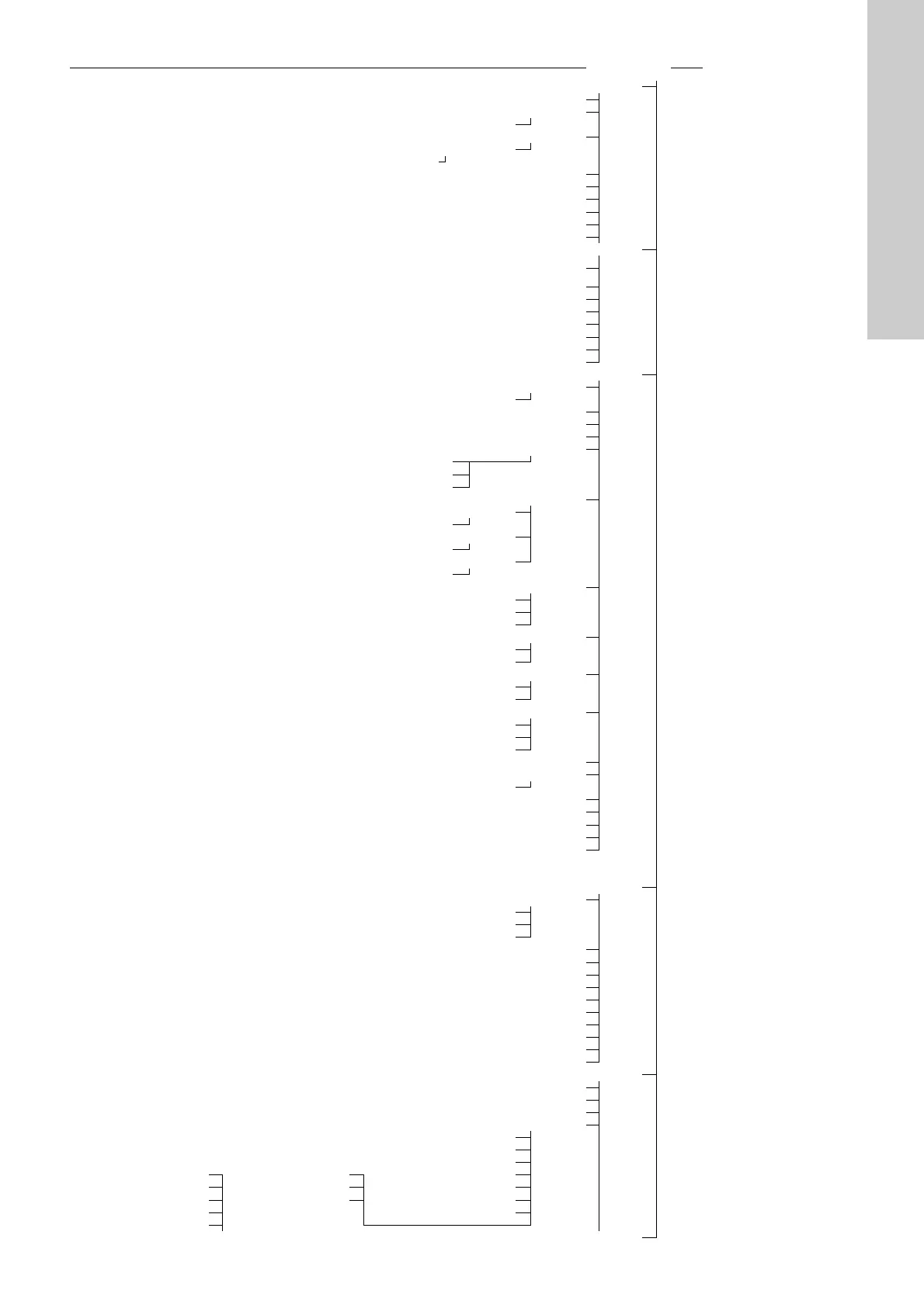
Primary controller 4.1
PI controller 4.1.1
Alternative setpoints 4.1.2
Alternative setpoints 2-7 4.1.2.1
External setpoint influence 4.1.3
Input value to be influenced by 4.1.3.1
Setting of influence function 4.1.3.2
Primary sensor 4.1.4
Secondary sensor 4.1.5
Clock program 4.1.6
Proportional pressure 4.1.7
S-system configuration 4.1.8
Setpoint ramp 4.1.9
Pump cascade control 4.2
Min. time between start/stop
4.2.1
Max. number of starts/hour
Standby pumps 4.2.3
Forced pump changeover 4.2.4
Pump test run 4.2.5
Pump stop attempt 4.2.7
Pump start and stop speed 4.2.8
Min. performance 4.2.9
Compensation for pump start-up time 4.2.10
Secondary functions 4.3
Stop function 4.3.1
Stop parameters 4.3.1.1
Pilot pump 4.3.2
Soft pressure build-up 4.3.3
Emergency run 4.3.5
Digital inputs 4.3.7
Function, DI1 (CU 352) - DI3, [10, 12, 14]
Function, DI1 (IO 351-41) - DI9, [10-46]
Function, DI1 (IO 351-42) - DI9, [10-46]
Analog inputs 4.3.8
Setting, AI1 (CU 352), [51] - AI3, [51, 54, 57]
Function, AI1 (CU 352) - AI3 [51, 54, 57]
Setting, AI1 (IO 351-41), [57] - AI2 [57, 60]
Function, AI1 (IO 351-41) - AI2 [57, 60]
Setting, AI1 (IO 351-42), [57] - AI2 [57, 60]
Function, AI1 (IO 351-42) - A2 [57, 60]
Digital outputs 4.3.9
DO1 (CU 352), [71] is signalling - DO2 [71, 74]
DO1 (IO 351-41), [77] is signalling - DO7 [77-88]
DO1 (IO 351-42), [77] is signalling - DO7 [77-88]
Analog outputs 4.3.10
AO1 (IO 351-41) [18] - AO3 [18, 22, 26]
AO1 (IO 351-42) [18] - AO3 [18, 22, 26]
Counter inputs 4.3.11
،ﻡﺟﺣﻟﺍ ﺩﺍﺩﻋDI1 [12 ,10] DI2 - [10] ,(IO 351-41)
،ﻡﺟﺣﻟﺍ ﺩﺍﺩﻋDI1 [12 ,10] DI2 - [10] ,(IO 351-42)
Min., max. and user-defined duty 4.3.14
Min. duty 4.3.14.1
Max. duty 4.3.14.2
Set user-defined duty 4.3.14.3
Pilot pump curve data 4.3.18
Pump curve data 4.3.19
Flow estimation 4.3.23
Control source 4.3.20
Fixed inlet pressure 4.3.22
Flow estimation 4.3.23
Reduced operation 4.3.24
Multisensor settings 4.3.25
Differential sensor 4.3.27
Customisable measured value type 4.3.28
Monitoring functions 4.4
Dry-running protection 4.4.1
Pressure/level switch 4.4.1.1
Measurement, inlet pressure 4.4.1.2
Measurement, tank level 4.4.1.3
Min. pressure 4.4.2
Max. pressure 4.4.3
External fault 4.4.4
Limit 1 exceeded 4.4.5
Limit 2 exceeded 4.4.6
Pumps outside duty range 4.4.7
Pressure relief 4.4.8
Log values 4.4.9
Fault, feedback sensor 4.4.10
Non-return valve 4.4.11
Functions, CU 352 4.5
Change language to the service language (English)
Run wizard again
Display language 4.5.1
Units 4.5.2
Pressure 4.5.2.1
Differential pressure 4.5.2.2
Head 4.5.2.3
Date and time 4.5.3 Temperature 4.5.2.8 Level 4.5.2.4
Password 4.5.4 Power 4.5.2.9 Flow rate 4.5.2.5
Ethernet 4.5.5 Energy 4.5.2.10 Volume 4.5.2.6
GENIbus number 4.5.6 Specific energy 4.5.2.7
Software status 4.5.9
Status display menu 4.6

 Loading...