English (GB)
8
5.3.3 Type key
Code Example Control MPC E 6x 000A DOL U1 W A O
Type range
E
EC
F
EF
S
E2
System type
All pumps with E motor
All pumps with CUE
Fixed-speed pumps, 1 CUE
All VFD non CUE
Fixed-speed pumps
2000 series
Number of main pumps
Main pump current
E
DOL
SD
SST
Start method
Electronic
Direct-on-line starter
Star-delta starter
Soft starter
U11
U12
U13
U14
U15
U16
UX
Voltage supply
3 x 400 V, 50 Hz, PE
3 x 400 V, 60 Hz, PE
3 x 400 V, 50 Hz, N, PE
3 x 400 V, 60 Hz, N, PE
3 x 380 V, 50 Hz, PE
3 x 380 V, 50 Hz, N, PE
-
W
F
O
X
Design
Wall mounting
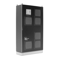
Floor standing
Outdoor
Customized
A
B
C
D
E
F
Standard versions
Standard version A
O10: Dry-running protection, digital input (or O9)
O9: Dry-running protection, inlet-pressure sensor (or O10)
O1: Redundant primary sensor (prepared fo connection only)
O2: Show repair switches in wiring diagram
Standard version B
O10: Dry-running protection, digital input (or O9)
O9: Dry-running protection, inlet-pressure sensor (or O10)
O1: Redundant primary sensor (prepared for connection only)
O2: Show repair switches in wiring diagram
O3: Emergency operation switch (mounted in panel)
Standard version C
O10: Dry-running protection, digital input (or O9)
O9: Dry-running protection, inlet-pressure sensor (or O10)
O1: Redundant primary sensor (prepared for connection only)
O2: Show repair switches in wiring diagram
O12: Operation light pump (lamp in front door)
O11: Fault light pump (lamp in front door)
O16: Voltmeter (in front door)
O15: Ammeter (in front door)
Standard version D
O10: Dry-running protection, digital input
O9: Dry-running protection, inlet-pressure sensor
O1: Redundant primary sensor
O2: Show repair switches in wiring
O3: Emergency operation switch
O4: IO 351B interface
Standard version E
O7: Dry-running protection, electrode relay
O1: Redundant primary sensor
O2: Show repair switches in wiring diagram
O3: Emergency operation switch
Standard version F
O8: Dry-running protection, vibration limit switch
O1: Redundant primary sensor
O2: Show repair switches in wiring diagram
O3: Emergency operation switch
O
Option
See 5.3.4 Optional equipment

 Loading...