English (GB)
9
5.3.4 Optional equipment
Operating-panel options
Included in pre-
defined Control
MPC standard
Option Description Location
Options
(type key
for Control
MPC)
ABEF
Redundant primary
sensor
-
The redundant primary sensor is visible
on the wiring diagram.
Note: The redundant primary sensor is
not included.
In the
control
cabinet
O1
●●●●
Show repair
switches in wiring
diagram
-
The repair switches are visible on the
wiring diagram.
Note: Repair switches are not included.
In the
control
cabinet
O2
●●●●
Emergency-
operation switch
-
The emergency-operation switch
enables emergency operation if a fault
occurs in the CU 352.
Note: The motor protection and the dry-
running protection are not activated
during emergency operation.
Note: One switch for each pump.
In the
control
cabinet
O3 -
●●●
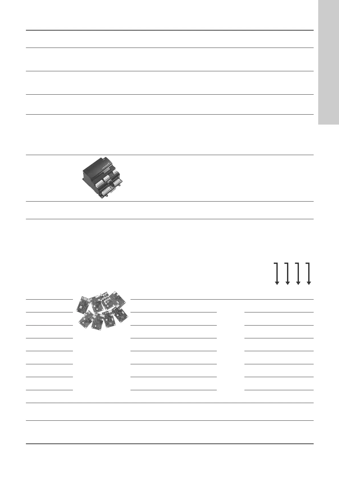
IO 351B interface
This option features a factory-fitted and
non-programmed IO 351B interface
enabling exchange of additional digital
in-/outputs, seven additional outputs,
two additional analog inputs and three
analog outputs.
Note: The CU 352 supports up to two
IO 351B interfaces.
In the
control
cabinet
O4 ----
Potential-free
contacts
-
Potential-free contacts are used to
indicate that the pumps in the system
are running or that an alarm is present.
In the
control
cabinet
O5 ----
CIM -
Communication
interface modules
The CIM modules enable
communication of operating data, such
as measured values and setpoints,
between Hydro MPC and a building-
management system.
Note: CIM modules must be fitted by
authorised staff. The CIM module
enables transfer of data such as:
• operating mode
• setpoint
• control mode
• warnings and alarms
• power/energy consumption.
We offer the following CIM modules:
O6
• CIM 050 GENIbus module
In the
control
cabinet
O6a ----
•CIM 110 LonWorks module O6b ----
•CIM 150 PROFIBUS DP Module O6c ----
• CIM 200 Modbus RTU Module O6d ----
•CIM 260
3G/4G GRM Grundfos Remote
Management
O6e ----
•CIM 280
3G/4G GRM Grundfos Remote
Management
O6f ----
•CIM 300 BACnet MS/TP Module O6g ----
• CIM 500 Ethernet module O6h ----
Dry-running
protection - electrode
relay
-
Electrode Relay mounted in panel.
Note: Order electrodes separately.
In the
control
cabinet
O7 - -
●
-
Dry-running
protection - vibration-
limit switch
-
The vibration-limit switch is visible on
the wiring diagram.
Note: Vibration-limit switch not
included.
In the
control
cabinet
O8 ---
●

 Loading...
