15
11.3 Description of functions
The description of functions is based on the four main menus of
the CU 351 control unit: Status, Operation, Alarm and Settings.
The functions apply to all control variants unless otherwise
stated.
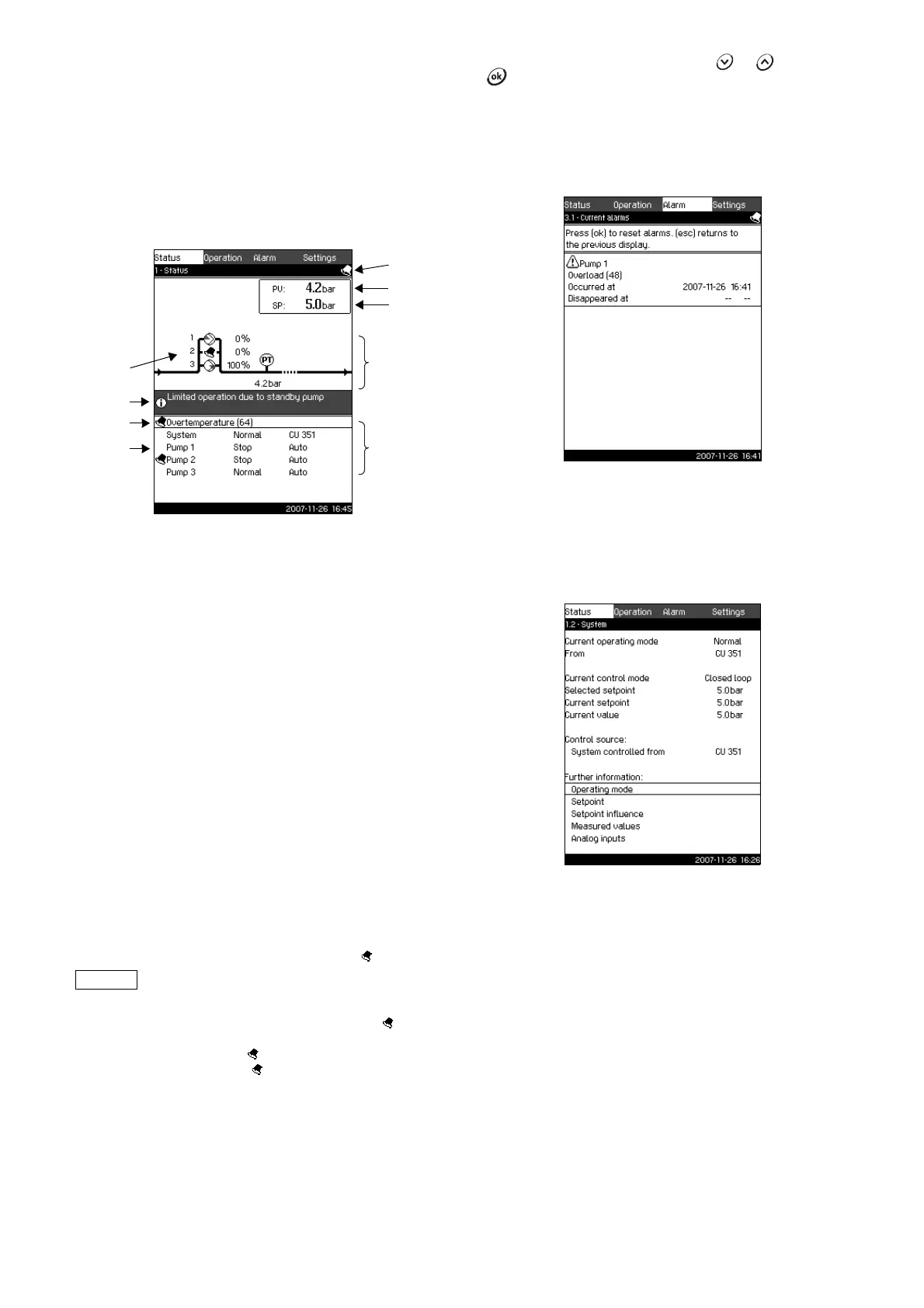
11.4 Status (1)
The first status display is shown below. This display is shown
when the Control MPC is switched on, and it appears when the
buttons of the control panel have not been touched for
15 minutes.
Fig. 6 Status
Description
No settings can be made in this menu.
The current value (process value, PV) of the control parameter,
usually the discharge pressure, is shown in the upper right corner
(G) together with the selected setpoint (SP) (H).
The upper half of the display (A) shows a graphic illustration of
the pump system. The selected measuring parameters are shown
with sensor symbol and current value.
In the middle of the display, an information field (I) will be shown if
any of the following events occur
• limited operation due to standby pump
• proportional pressure influence active
• external setpoint influence active
• alternative setpoint active
• clock program active
• remote-controlled via Ethernet
• remote-controlled via GENI (RS-485).
The lower display half (B) shows
• the latest current alarm, if any, and the fault cause together
with the fault code in brackets
• system status with current operating mode and control source
• pump status with current operating mode and manual/auto.
If the fault is related to one of the pumps, the symbol will also
be shown in front of the status line (D) of the pump in question.
At the same time, the symbol will be flashing instead of the
pump symbol (E). The symbol will be shown to the right in the
top line of the display (F). As long as a fault is present, this
symbol will be shown in the top line of all displays.
To open a menu line, mark the line with or , and press
.
The display makes it possible to open status displays showing
• current alarms
• system status
• status of each pump.
11.4.1 Current alarms (3.1)
Fig. 7 Current alarms
Description
In this display, current unreset alarms and warnings are shown.
For further information, see sections 11.6.2 Current alarms (3.1)
and 11.6.3 Alarm log (3.2).
11.4.2 System (1.2)
Fig. 8 System
Description
This display shows the current operational state of the system. It
is possible to go to subdisplays showing details.
The display makes it possible to open specific displays about
• operating mode
•setpoint
• setpoint influence
• measured values
• analog inputs.
TM03 8947 4707
If a fault has occurred, the symbol will be
shown in the alarm line (C) together with the
cause and fault code, for instance
Overtemperature (64).
TM03 2293 4807TM03 8946 4807