40
11.7.25 Emergency run (4.3.5)
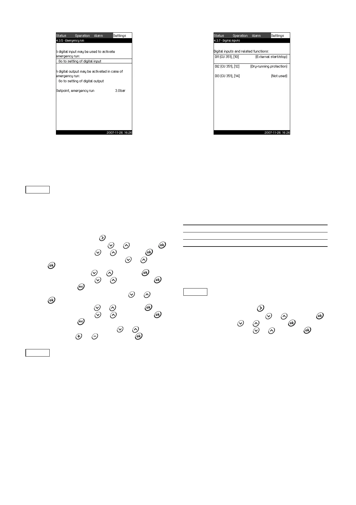
Fig. 66 Emergency run
Description
This function is used in booster applications. When this function
has been activated, the pumps will keep running regardless of
warnings or alarms. The pumps will run according to a setpoint
set specifically for this function.
Setting range
• Setting of digital input (11.7.26 Digital inputs (4.3.7)).
• Setting of digital output (11.7.31 Digital outputs (4.3.9)).
• Setting of setpoint for emergency run.
Setting via control panel
1. Mark the Settings menu with
2. Mark Secondary functions with or , and press .
3. Mark Emergency run with or , and press .
4. Mark Go to setting of digital input with or , and
press .
5. Select a digital input with or , and press .
6. Mark Emergency run with or , and save with .
7. Return by pressing twice.
8. Mark Go to setting of digital output with or , and
press .
9. Select a digital output with or , and press .
10.Mark Emergency run with or , and save with .
11. Return by pressing twice.
12.Mark Setpoint, emergency run with or .
13.Set the value with or , and save with .
11.7.26 Digital inputs (4.3.7)
Fig. 67 Digital inputs
Description
In this menu, the digital inputs of the CU 351 can be set. Each
input, except DI1, can be activated and related to a certain
function.
As standard, the Control MPC has three digital inputs. If the
Control MPC incorporates an IO 351B module (option), the
number of digital inputs is 12.
In the display, all digital inputs are shown so that their physical
position in the Control MPC can be identified.
Example
DI1 (IO 351-41), [10]:
For further information on the connection of various digital inputs,
see the wiring diagram supplied with the control cabinet.
Setting range
The digital input to be set is selected in the display Digital inputs
(4.3.7).
Setting via control panel
1. Mark the Settings menu with .
2. Mark Secondary functions with or , and press .
3. Mark Digital inputs or , and press .
4. Select the digital input with or , and press .
TM03 8971 4807
In case of sensor fault, both main and standby
pumps will run at 100 % speed!
When this function has been set as described
above, it can also be activated via the display
System operating mode (2.1.1).
TM03 2359 4607
DI1: Digital input No 1
(IO 351-41): IO 351, GENIbus number 41
[10]: Terminal No 10
DI1 (CU 351) cannot be selected.