29
11.7.6 Setting of influence function (4.1.3.2)
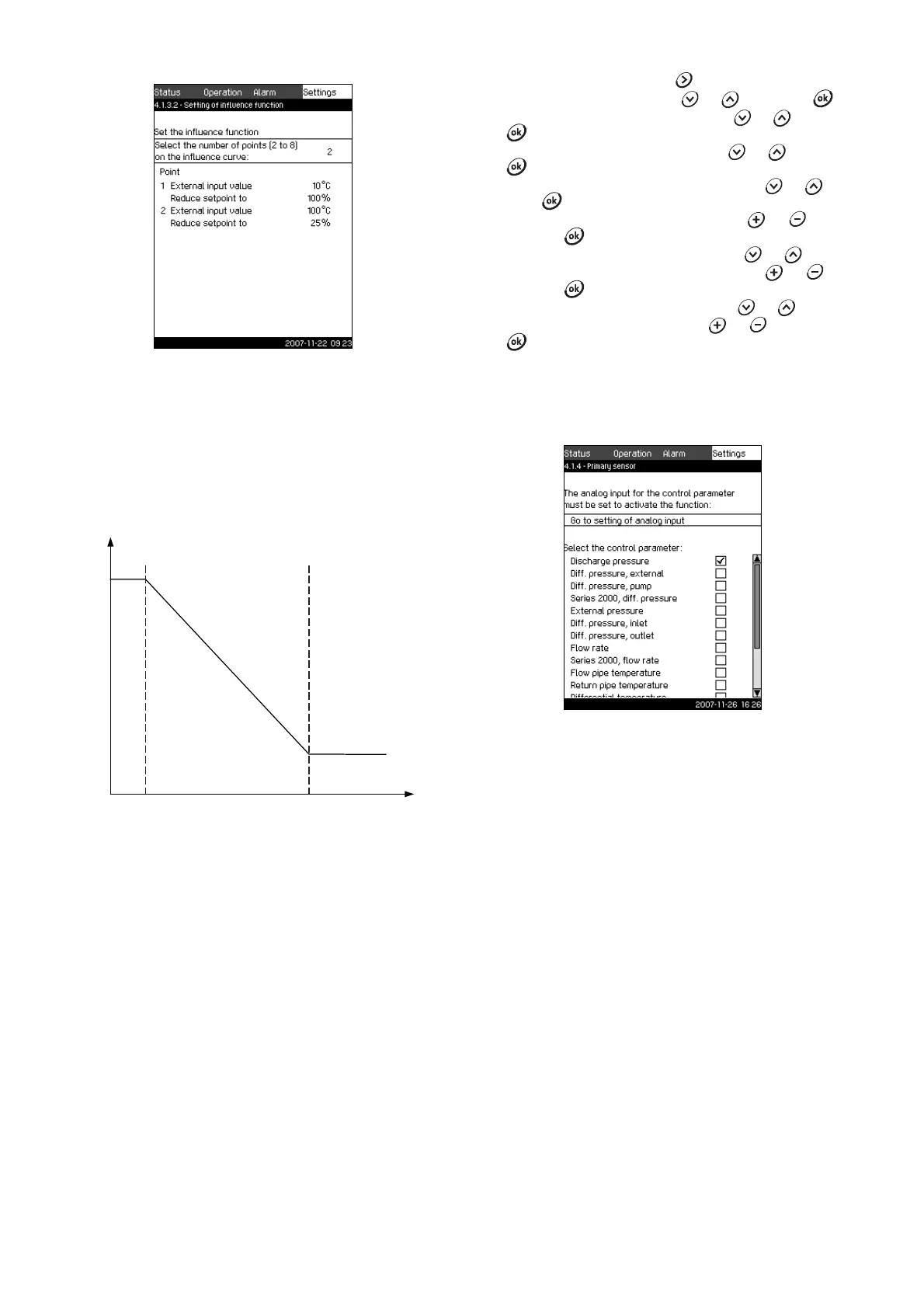
Fig. 37 Setting of influence function
Description
In this menu, you select the relation between the measuring
parameter which is to influence the setpoint and the desired
influence as a percentage.
The relation is set by entering values in a table with maximum
eight points by means of the control panel.
Example:
Fig. 38 Relation between setpoint influence and flow rate
The control unit draws straight lines between the points. A
horizontal line is drawn from the minimum value of the relevant
sensor (0 m
3
/h in the example) to the first point. This is also the
case from the last point to the sensor's maximum value (example
50 m
3
/h).
Setting range
Two to eight points can be selected. Each point contains the
relation between the value of the parameter which is to influence
the setpoint and the influence of the value.
Setting via control panel
1. Mark the Settings menu with .
2. Mark Primary controller with or , and press .
3. Mark External setpoint influence with or , and press
.
4. Mark Set the influence function with or , and press
.
5. Mark the menu line for number of points with or , and
press .
6. Select the required number of points with or , and
save with .
7. Mark External input value (point 1) with or .
8. Set the value of the external input value with or , and
save with .
9. Mark Reduce setpoint to (point 1) with or .
10. Set the value as a percentage with or , and save with
.
11. Repeat steps 7 to 10 for all desired parameters.
Factory setting
External setpoint influence is not activated.
11.7.7 Primary sensor (4.1.4)
Fig. 39 Primary sensor
Description
In this display, select the control parameter of the system and set
the sensor to measure the value.
For booster systems, the control parameter is usually the
discharge pressure which is measured by a sensor fitted on the
discharge manifold. In heating and cooling systems, the control
parameter is typically a differential pressure or a temperature.
See section 12. Measuring parameters.
Setting range
• Discharge pressure
• Differential pressure, external
• Differential pressure, pump
• Series 2000, differential pressure
• External pressure
• Differential pressure, inlet
• Differential pressure, outlet
•Flow rate
• Series 2000, flow rate
• Flow pipe temperature
• Return pipe temperature
• Differential temperature
• Ambient temperature
• Return pipe temperature, external
• 0-100 % signal
• Not used.
TM03 9963 4707TM03 9978 4707
Temperature [°C]
Setpoint influence [%]
TM03 8958 4807