61
12. Measuring parameters
12.1 Transmitter types
The transmitter types in the table below can be used for the
measurement of values in the system.
12.2 Parameter list
The table below shows which measured values the CU 351 can
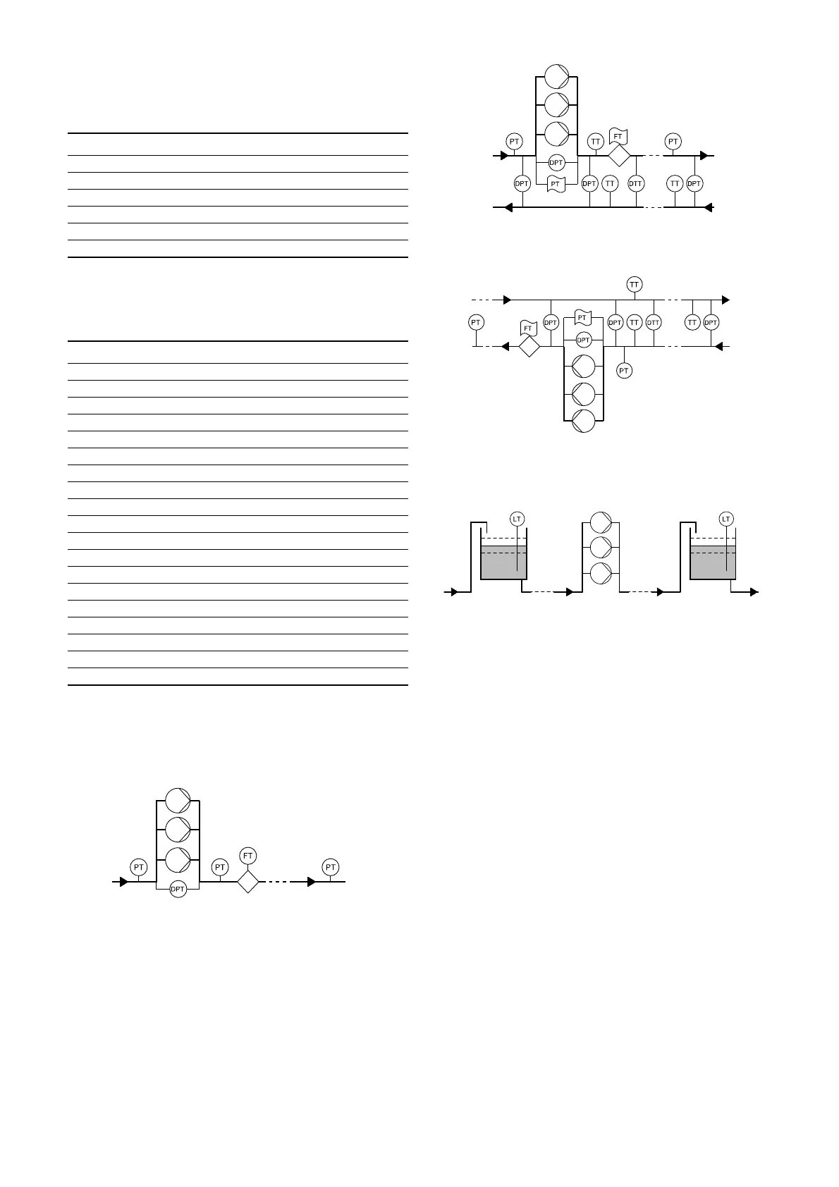
receive via its analog inputs. Figures 114 to 115 117 show where
the values can be measured.
* The ambient temperature is typically the temperature in the
room where the Control MPC is located.
** A 0-100 % signal from an external controller. It can for instance
be a 0-10 V signal.
Fig. 114 Pressure boosting
Fig. 115 Heating and cooling, pumps in flow pipe
Fig. 116 Heating and cooling, pumps in return pipe
Fig. 117 Level monitoring
Abbreviation Transmitter
DPT Differential pressure transmitter
DTT Differential temperature transmitter
FT Flow transmitter
LT Level transmitter
PT Pressure transmitter
TT Temperature transmitter
No Parameter
1Flow rate
2 Discharge pressure
3 Differential pressure, external
4 Inlet pressure
5 Differential pressure, pump
6 Differential pressure, inlet
7 Differential pressure, outlet
8 Tank level, discharge side
9 Tank level, suction side
10 Return pipe temperature, external
11 Flow pipe temperature
12 Return pipe temperature
13 Differential temperature
14 External pressure
15 Series 2000, differential pressure
16 Series 2000, flow rate
17 System pressure
Not shown Ambient temperature*
Not shown 0-100 % signal**
TM03 8823 3507
TM03 9964 4707TM03 9965 4707TM03 8824 2607