43
11.7.31 Digital outputs (4.3.9)
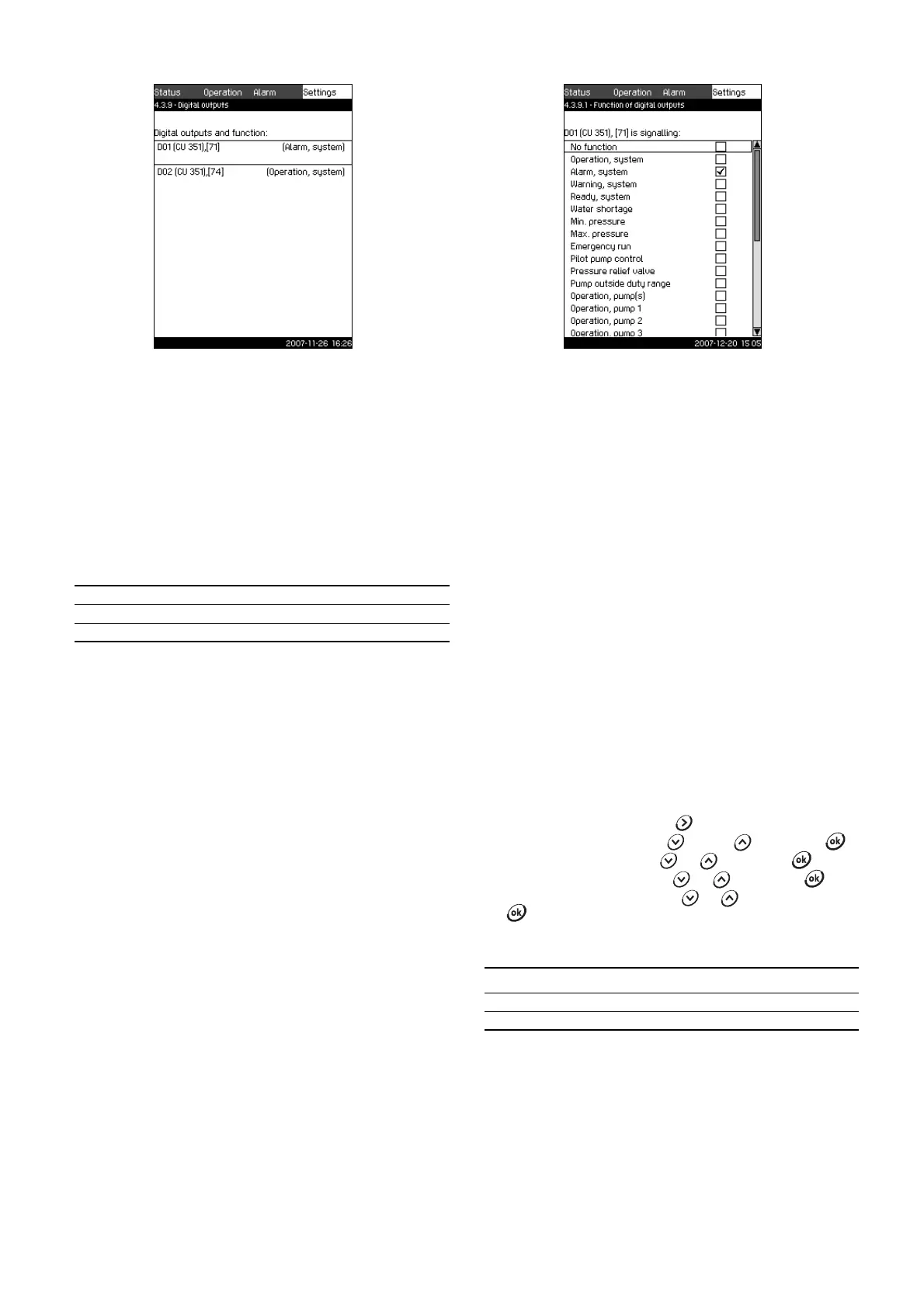
Fig. 72 Digital outputs
Description
In this display, the digital relay outputs of the Control MPC can be
set. Each output can be activated and related to a certain
function.
As standard, the Control MPC has two digital outputs.
If the Control MPC incorporates an IO 351B module (option), the
number of digital outputs is 9.
In the display, all digital outputs are shown so that their physical
position in the Control MPC can be identified.
Example
DO1 (IO 351-41) [71]:
For further information on the connection of various digital
outputs, see the wiring diagram supplied with the CU 351.
Setting range
In the display Digital outputs (4.3.9), the digital output to be used
is selected.
11.7.32 Functions of digital outputs (4.3.9.1 to 4.3.9.16)
Fig. 73 Functions of digital outputs
Description
In the displays Functions of digital outputs (4.3.9.1 to 4.3.9.16), a
function can be related to the individual outputs.
Setting range
It is possible to select one function in each display:
• No function
• Operation, system
• Alarm, system
• Warning, system
• Ready, system
• Water shortage
•Min. pressure
• Max. pressure
• Emergency run
• Pilot pump control
• Pressure relief valve
• Operation, pump 1 to 6
• Alarm, pump 1 to 6
• Alarm, limit 1 exceeded
• Warning, limit 1 exceeded
• Alarm, limit 2 exceeded
• Warning, limit 2 exceeded.
Setting via control panel
1. Mark the Settings menu with .
2. Mark Secondary functions with or , and press .
3. Mark Digital outputs with or , and press .
4. Select the digital output with or , and press .
5. Mark the desired function with or , and activate it with
.
The activation is indicated by a check mark in the box.
Factory setting
TM03 2333 4607
DO1 Digital output No 1
(IO 351-41) IO 351B, GENIbus number 41
[71] Terminal No 71
TM03 8974 4807
Digital output Function
DO1 (CU 351) [71] Alarm, system
DO2 (CU 351) [74] Operation, system