37
11.7.22 Secondary functions (4.3)
Fig. 58 Secondary functions
Description
Functions that are secondary in relation to the normal operation
of the system can be set in this display. Secondary functions are
functions that offer additional functionality.
The display makes it possible to open these specific displays:
• Stop function (4.3.1)
• Soft pressure build-up (4.3.3)
• Digital inputs (4.3.7)
• Analog inputs (4.3.8)
• Digital outputs (4.3.9)
• Emergency run (4.3.5)
• Min., max. and user-defined duty (4.3.14)
• Pump curve data (4.3.19)
• Flow estimation (4.3.23)
• Control source (4.3.20)
• Fixed inlet pressure (4.3.22).
11.7.23 Stop function (4.3.1)
Fig. 59 Stop function
Description
This function is typically used in constant pressure applications
and makes it possible to stop the last pump if there is no or a very
small consumption. The purpose is to
• save energy
• prevent heating of shaft seal faces due to increased
mechanical friction as a result of reduced cooling by the
pumped liquid
• prevent heating of the pumped liquid.
The description of the stop function applies to all booster systems
with variable-speed pumps. Control MPC-S will have on/off
control of all pumps as described in section 8. Overview of control
variants.
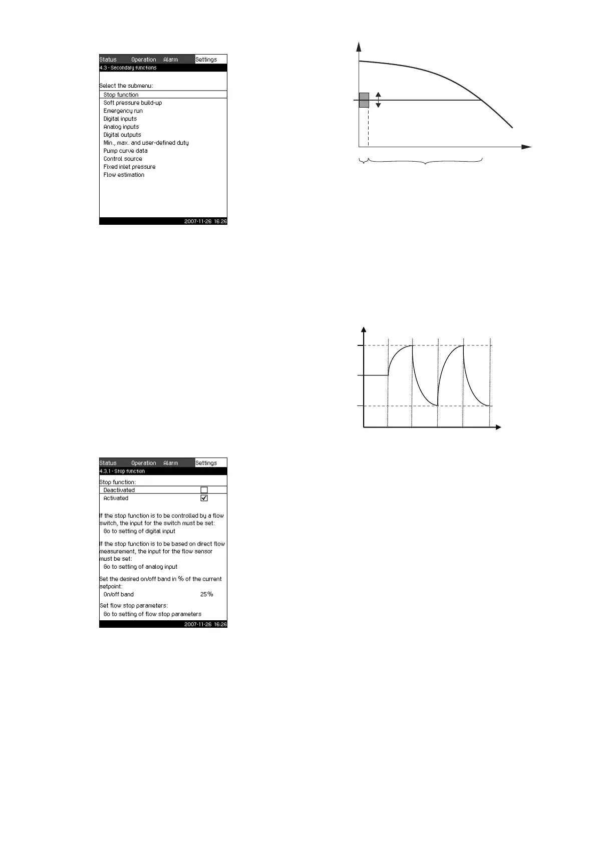
Fig. 60 On/off band
When the stop function is activated, the operation is continuously
monitored to detect a low flow rate. When the CU 351 detects no
or a low flow rate (Q < Q
min
), it changes from constant-pressure
operation to on/off control of the last pump in operation.
Before stopping, the pump increases the pressure to a value
corresponding to H
set
+ 0.5 x on/off band. The pump is restarted
when the pressure is H
set
– 0.5 x on/off band. See fig. 61.
Fig. 61 On/off operation
The flow rate is estimated by the CU 351 when the pump is in the
stop period. As long as the flow rate is lower than Q
min
, the pump
will run on/off. If the flow rate is increased to above Q
min
, the
pump returns to normal operation, H
set
. H
set
is equal to the
current setpoint. See section 11.4.4 Setpoint (1.2.2).
Detection of low flow rate
Low flow rate can be detected by means of
• direct flow measurement with a flowmeter or flow switch
• estimation of flow rate by measurement of pressure and
speed.
If the booster system is not connected to a flowmeter or flow
switch, the stop function will use the estimating function.
If the detection of low flow rate is based on flow estimation, a
diaphragm tank of a certain size and with a certain precharge
pressure is required.
TM03 8969 4807TM03 2355 4607
TM03 1692 2705TM03 9292 4807
H
Q
H
set
Q
min
On/off band
On/off
control
Normal operation
Stop = H
set
+ 0.5 x on/off band
Start = H
set
– 0.5 x on/off band
Stop
Start
H [m]
Time [sec]
AB C B C
A: Normal operation
B: Pressure boosting
C: Stop