26
11.7.2 PI controller (4.1.1)
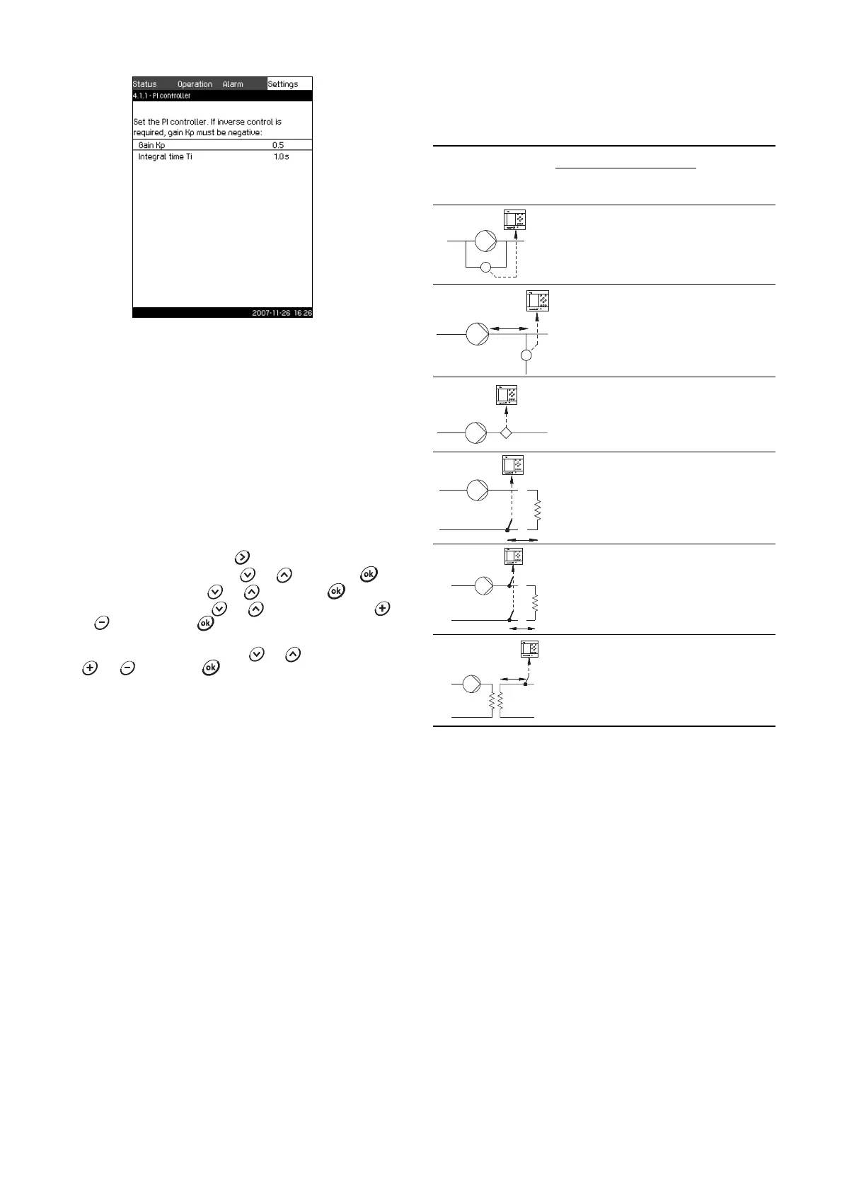
Fig. 33 PI controller
Description
Control MPC includes a standard PI controller which ensures that
the pressure is stable and corresponds to the setpoint.
It is possible to adjust the PI controller if a faster or slower
reaction to changes of consumption is required.
A faster reaction is obtained if K
p
is increased and T
i
is reduced.
A slower reaction is obtained if K
p
is reduced and T
i
is increased.
Setting range
• Gain K
p
: –30 to 30.
Note: For inverse control, set K
p
to a negative value.
• Integral time T
i
: 0.1 to 3600 seconds.
Setting via control panel
1. Mark the Settings menu with .
2. Mark Primary controller with or , and press .
3. Mark PI controller with or , and press .
4. Select the gain (K
p
) with or . Set the value with
or , and save with .
Note: Usually it is not necessary to adjust K
p
.
5. Select the integral time (T
i
) with or . Set the time with
or , and press .
Factory setting
The setting of K
p
and T
i
depends on the system and application.
PI controller settings for pressure boosting
If the application has been set to pressure boosting in the start-up
wizard, the following values of K
p
and T
i
will be set automatically:
•K
p
: 0.5
•T
i
: 1 second.
PI controller settings for heating and cooling
If another application than pressure boosting has been selected
in the start-up wizard, the values of K
p
and T
i
will be set
automatically according to the table below. As Control MPC does
not know the pipe length, the default parameters will be set
according to the table to a pipe length (L
1
or L
2
) of 5 metres.
1)
Heating systems are systems in which an increase in pump
performance will result in a temperature rise at the sensor.
2)
Cooling systems are systems in which an increase in pump
performance will result in a temperature drop at the sensor.
L
1
: Distance [m] between pump and sensor.
L
2
: Distance [m] between heat exchanger and sensor.
ΔP: Measurement of differential pressure.
Q: Measurement of flow rate.
t: Measurement of temperature.
Δ
t: Measurement of differential temperature.
TM03 2387 4607
System/application
K
p
T
i
[Seconds]
Heating
system
1)
Cooling
system
2)
0.5 1
0.5
L
1
< 5 m: 1
L
1
> 5 m: 3
L
1
> 10 m: 5
0.5 1
0.5 -0.5 10 + 5L
2
0.5 10 + 5L
2
0.5 -0.5 30 + 5L
2