48
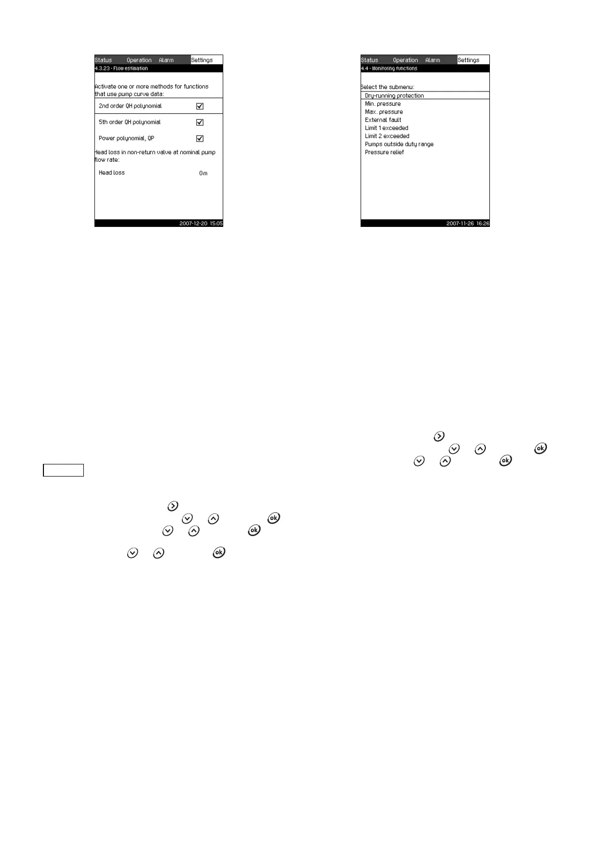
11.7.40 Flow estimation (4.3.23)
Fig. 85 Flow estimation
Description
As described in section 11.7.37 Pump curve data (4.3.19), the
CU 351 can optimise operation according to performance curves
and motor data. In this display, curve types are selected which
the CU 351 will use for the optimisation if they are available.
At large flow rates, there may be a considerable head loss
between the pump discharge flange and the pressure sensor. The
loss is caused by non-return valves and pipe bends. To improve
the flow estimation of the system, it is necessary to compensate
for the difference between the measured and the actual
differential pressure across the pump. This is done by entering
the head loss in non-return valves and pipe bends at the rated
flow rate of one pump.
Setting range
• 2nd order QH polynomial
• 5th order QH polynomial
• Power polynomial, QP
• Head loss.
Setting via control panel
1. Mark the Settings menu with .
2. Mark Secondary functions with or , and press .
3. Mark Flow estimation with or , and press .
4. Select the curve type by marking one of the lines at the
selection box with or , and press .
Factory setting
All polynomials are selected.
11.7.41 Monitoring functions (4.4)
Fig. 86 Monitoring functions
Description
Control MPC has a series of functions that constantly monitor the
operation of the system.
The primary purpose of the monitoring functions is to ensure that
faults do not damage pumps or the system.
Setting range
The following functions can be selected:
• Dry-running protection (4.4.1)
• Min. pressure (4.4.2)
• Max. pressure (4.4.3)
• External fault (4.4.4)
• Limit 1 and 2 exceeded (4.4.5 and 4.4.6)
• Pumps outside duty range (4.4.7)
• Pressure relief (4.4.8).
Setting via control panel
1. Mark the Settings menu with .
2. Mark Monitoring functions with or , and press .
3. Select the function with or , and press .
TM03 8977 4807
It is possible to select several curve types, as the
CU 351 makes a priority based on the data
available.
TM03 8978 4807