10
10.1 Display (pos. 1)
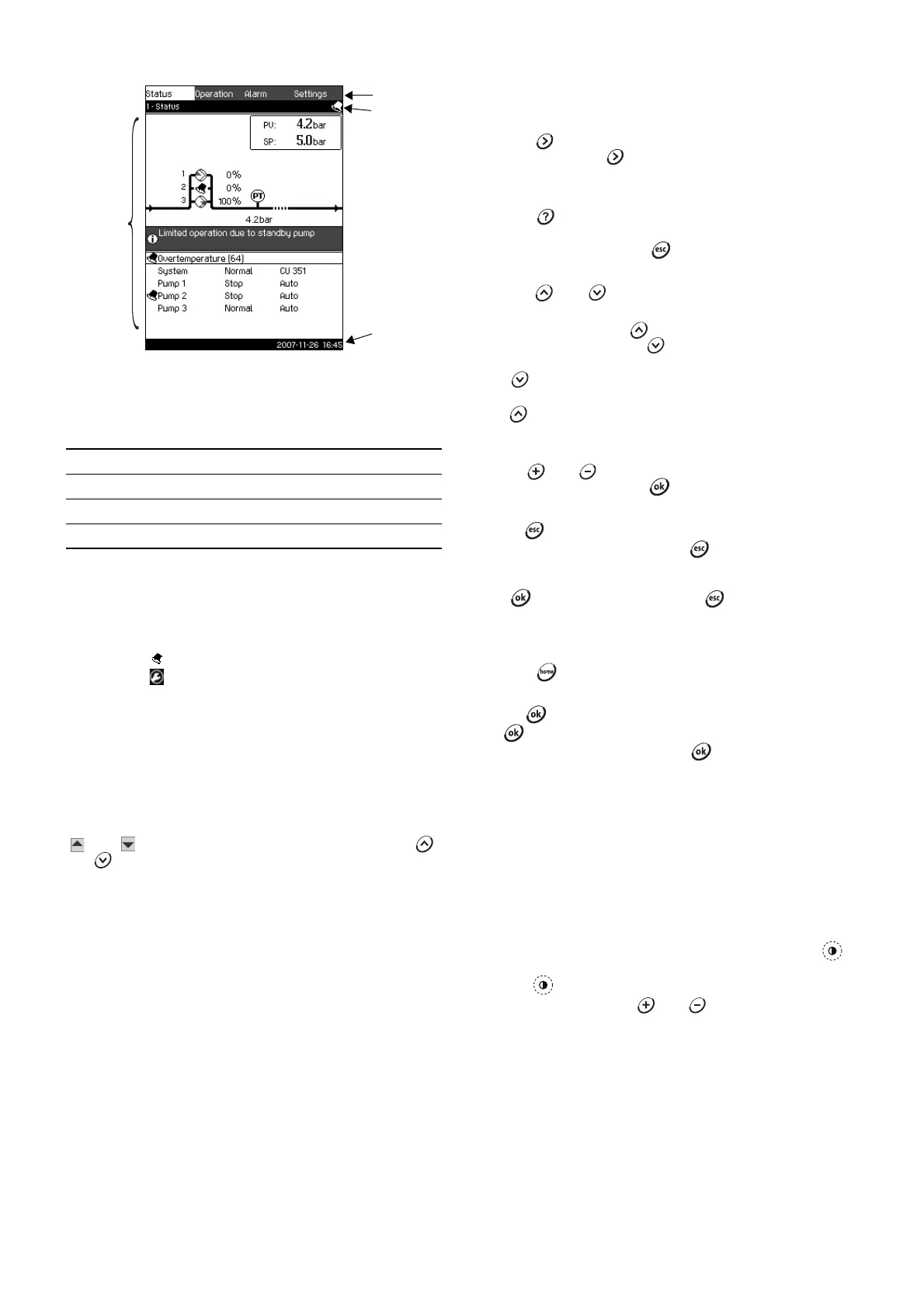
Fig. 5 Display design
10.1.1 Menu line
The menu line (A) is illustrated in fig. 5.
The display has four main menus:
10.1.2 Top line
The top line (B) is illustrated in fig. 5.
The top line shows
• the display number and title (left side)
• the selected menu (left side)
• the symbol in case of alarm (right side)
• the symbol if the service language has been selected
(right side).
10.1.3 Graphical illustration
The graphical illustration (D) may show a status, an indication or
other elements, depending on the position in the menu structure.
The illustration may show the entire system or part of it as well as
various settings.
10.1.4 Scroll bar
If the list of illustration elements exceeds the display, the symbols
and will appear in the scroll bar to the right. Use the
and buttons to move up and down in the list.
10.1.5 Bottom line
The bottom line (C) shows the date and time.
10.2 Buttons and indicator lights
The buttons (pos. 2 to 10 in fig. 4) on the CU 351 are active when
they are illuminated.
10.2.1 Arrow to the right (pos. 2)
Press the button to move to the next menu in the menu
structure. If you press when the Settings menu is
highlighted, you go to the Status menu.
10.2.2 Help (pos. 3)
When the button is illuminated, a help text applying to the
current display will appear if the button is pressed.
Close the text by pressing the button.
10.2.3 Up and down (pos. 4 and 5)
Press the and buttons to move up and down in lists.
A text can be selected when it is in a box.
If a text is marked and the button is pressed, the text above
will be marked instead. If the button is pressed, the text
below will be marked.
If the button is pressed in the last line in the list, the first line
will be marked.
If the button is pressed in the first line in the list, the last line
will be marked.
10.2.4 Plus and minus (pos. 6 and 7)
Use the and buttons to increase and reduce values.
A value is activated when the button is pressed.
10.2.5 Esc (pos. 8)
Use the button to go one display back in the menu.
If a value has been changed and the button is pressed, the
new value will not be saved. For further information, see section
10.2.7 Ok (pos. 10).
If the button is pressed before the button, the new
value will be saved. For further information, see section
10.2.7 Ok (pos. 10).
10.2.6 Home (pos. 9)
Press the button to return to the Status menu.
10.2.7 Ok (pos. 10)
Use the button as an enter button.
The button is also used to start the setting of a value.
If a value has been changed and the button is pressed, the
new value will be activated.
10.2.8 Indicator lights (pos. 11 and 12)
The control panel incorporates a green and red indicator light.
The green indicator light is on when the Control MPC is in
operation.
The green indicator light is flashing if the Control MPC has been
set to stop.
The red indicator light is on if there is an alarm or a warning.
The fault can be identified from the alarm list.
10.2.9 Contrast (pos. 13)
The contrast in the display can be changed by means of the
button:
1. Press .
2. Adjust the contrast with and .
10.2.10 Back light
If no button is touched for 15 minutes, the back light of the panel
will be dimmed, and the first display in the Status menu will
appear.
Press any button to re-activate the back light.
TM03 8947 4807
Status: Indication of system status
Operation: Change of operating parameters such as setpoint
Alarm: Alarm log for fault finding
Settings: Change of settings (password option)