42
11.7.29 Analog inputs (4.3.8.1 to 4.3.8.7)
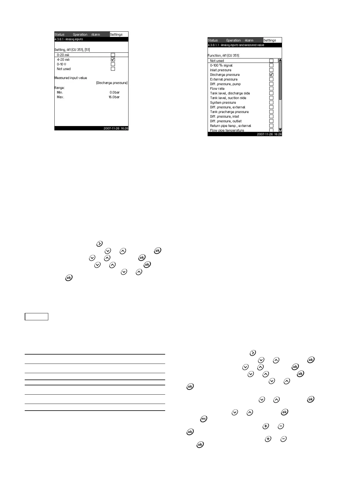
Fig. 70 Analog inputs
Description
In the displays 4.3.8.1 to 4.3.8.7, analog inputs can be set.
Each display is divided into three parts:
• Setting of input signal, for instance 4-20 mA
• Measured input value, for instance discharge pressure
• Measuring range of the sensor/signal transmitter, for instance
0-16 bar.
Setting range
It is possible to set the following parameters in each display:
• Not used
• Range of input signal, 0-20 mA, 4-20 mA, 0-10 V
• Measured input value
• Sensor range.
Setting via control panel
1. Mark the Settings menu with .
2. Mark Secondary functions with or , and press .
3. Mark Analog inputs with or , and press .
4. Select the analog input with or , and press .
5. Mark the setting of the analog input with or , and
activate it with .
The activation is indicated by a check mark in the box.
Factory setting
11.7.30 Analog inputs and measured value (4.3.8.1.1 to
4.3.8.7.1)
Fig. 71 Analog inputs and measured value
Description
In the display Analog inputs and measured value (4.3.8.1.1 to
4.3.8.7.1), a function can be related to the individual analog
inputs.
Setting range
It is possible to select one function per analog input. For further
details, see section 12. Measuring parameters.
• Not used
• 0-100 % signal
• Inlet pressure
• Discharge pressure
• External pressure
• Differential pressure, pump
•Flow rate
• Tank level, discharge side
• Tank level, suction side
• System pressure
• Differential pressure, external
• Tank precharge pressure
• Differential pressure, inlet
• Differential pressure, outlet
• Return pipe temperature, external
• Flow pipe temperature
• Return pipe temperature
• Differential temperature
• Ambient temperature
• Power, pump 1 to 6
• Power, VFD.
Setting via control panel
1. Mark the Settings menu with .
2. Mark Secondary functions with or , and press .
3. Mark Analog inputs with or , and press .
4. Select the analog input with or , and press .
5. Set the range of the analog input with or , and press
.
The activation is indicated by a check mark.
6. Mark Measured input value with or , and press .
Now the display 4.3.8.1.1 appears.
7. Select the input with or , and press .
8. Press to return to display 4.3.8.1.
9. Set the minimum sensor value with or , and save with
.
10.Set the maximum sensor value with or , and save
with .
TM03 2357 4607
If an analog input is deactivated, the display will
only show the top part, i.e. the setting of the
analog input.
If the input is activated, the middle part,
"Measured input value", will be shown. This
makes it possible to relate a function to the
analog input in another display. When the analog
input has been related to a function, CU 351 will
return to the display for setting of analog inputs.
Pressure boosting
Analog input Function
AI1 (CU 351) [51] Discharge pressure
Heating and cooling
Analog input Function
AI1 (CU 351) [51] These are selected in the start-up wizard
TM03 8973 4807