7.12 Signal cables
Use screened cables with a cross-sectional area of minimum 28
AWG (0.5 mm
2
) and maximum 16 AWG (1.5 mm
2
) for the external
on/off switch, digital inputs, setpoint and sensor signals.
The wires in the motor terminal box must be as short as possible.
7.12.1 Connecting signal cables
1. Connect the screens of the cables to the frame at both ends
with good connection. The screens must be as close as
possible to the terminals.
TM082967
Model K
2. Connect the signal cables to the terminals.
3. Depending on the model, tighten one or two terminal screws.
7.12.2
Connection of Danfoss pressure sensor MBS3000 to an
E-pump
TM051533_2911
MBS3000 pressure sensor
Use screened cables with a cross-sectional area of minimum 28
AWG and maximum 16 AWG.
The blue wire of the pressure sensor is connected to terminal (AI1)
of the E-pump. The brown wire of the pressure sensor is connected
to terminal 24 V of the E-pump.
7.12.3
Connection of Grundfos pressure sensor ISP44 to an E-
pump
TM083396
ISP44 pressure sensor
Use unscreened cables with a cross-sectional area of minimum 28
AWG and maximum 16 AWG.
The blue wire of the pressure sensor is connected to terminal (AI1)
of the E-pump. The brown wire of the pressure sensor is connected
to terminal 24 V of the E-pump.
7.13
Bus connection cable
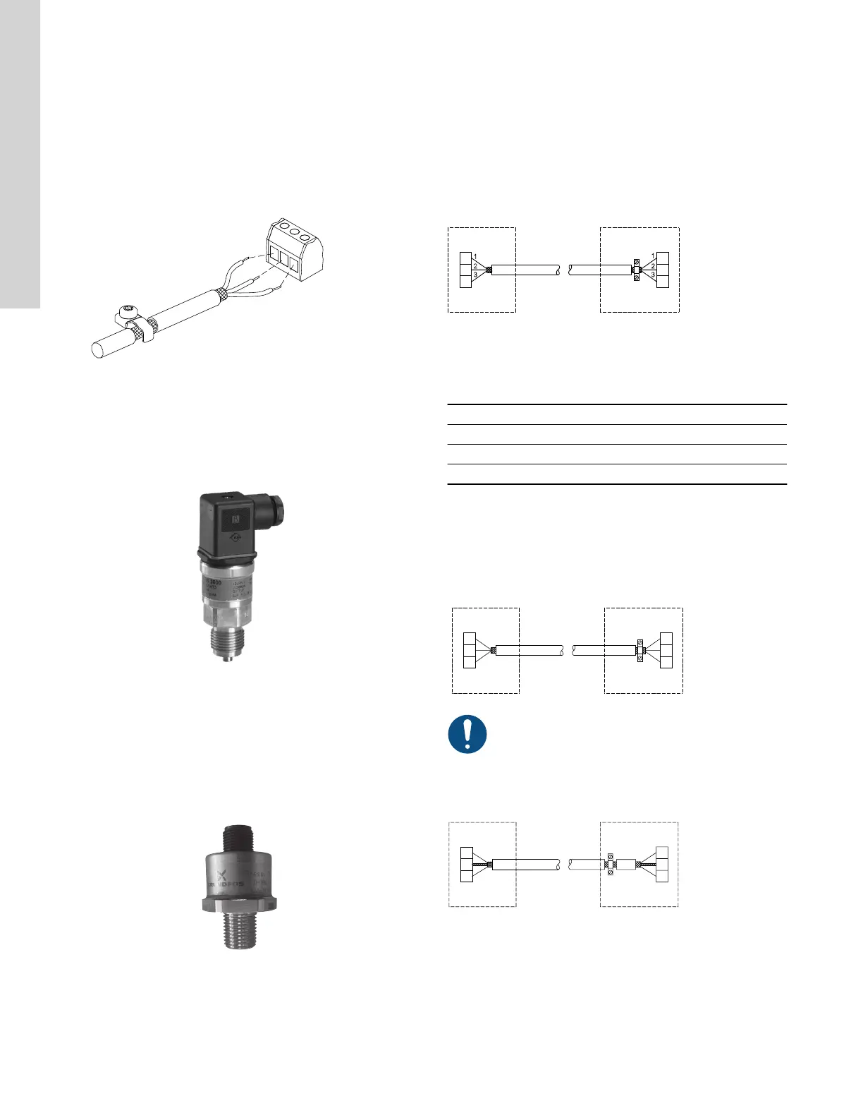
7.13.1 Connecting a 3-core bus cable, GENIbus
For the bus connection, use a screened 3-core cable with a cross-
sectional area of minimum 28 AWG (0.5 mm
2
) and maximum 16
AWG (1.5 mm
2
).
• If the motor is connected to a unit with a cable clamp which is
identical to the one on the product, connect the screen to the
cable clamp.
• If the unit has no cable clamp, leave the screen unconnected at
this end.
TM070223
7.13.2 Connecting a 3-core bus cable, Modbus
A screened, twisted-pair cable must be used. The cable screen
must be connected to protective earth at both ends.
Recommended connection
Terminal Modbus Colour code Data signal
A D1 Yellow Positive
B D0 Brown Negative
Y Common/GND Grey Common/GND
Fitting the cable
1. Connect the yellow conductor to terminals D1 and A.
2. Connect the brown conductor to terminals D0 and B.
3. Connect the grey conductor to terminals Common/GND and Y.
4. Connect the cable screens to protective earth via the earth
clamp.
TM083382
It is important to connect the screen to protective earth
through the earth clamp and to connect the screen to
protective earth in all units connected to the bus line.
7.13.3 Connecting a 2-core bus cable
• Connect a screened 2-core bus cable as follows:
TM070221
7.13.4
Bus signal
The product enables serial communication via an RS-485 input.
The communication is carried out according to the Grundfos
GENIbus protocol and enables connection to a building
management system or another external control system.
20
English (US)

 Loading...


