Pos. Description
X: External input signal from 0 to 100 %
Y: Setpoint influence from 0 to 100 %
X1: Actual input signal, 60 %
Y1: Fixed maximum speed in percentage
Y2: Setpoint speed in percentage
Y3: Actual setpoint speed in percentage
Y4: User-set minimum speed in percentage
10.17.1 Setpoint influence functions
10.17.1.1 Linear function
The setpoint is influenced linearly from 0 to 100 %.
100 %0
3.5 V
0.5
5 V
0
10 V0
20 mA
0
20 mA
4
-50
100
0
204 °C
X
Y
TM070255
Pos. Description
X: External input signal from 0 to 100 %
Y: Setpoint influence from 0 to 100 %
10.17.1.2 Linear with Stop
In the input signal range from 20 to 100 %, the setpoint is
influenced linearly. If the input signal is below 10 %, the motor
changes to the Stop operating mode. If the input signal increases
more than 15 %, the operating mode changes back to Normal.
100
3.5 V
5 V
10 V
20 mA
20 mA
B
2015100
0.5
0
0
0
4
-50
204 °C
Y
100
X
A, 0
TM070542
Pos.
Description
X: External input signal from 0 to 100 %
Y: Setpoint influence from 0 to 100 %
A: Normal
B: Stop
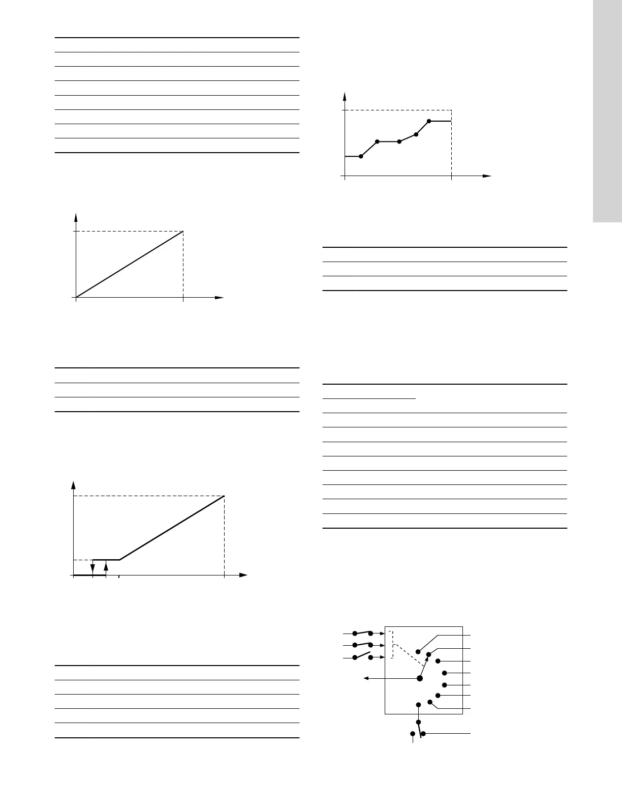
10.17.1.3 Influence table
The setpoint is influenced by a curve made of two to eight points.
There is a straight line between the points and a horizontal line
before the first point and after the last point.
100 %
0
3.5 V0.5
5 V0
10 V
0
20 mA0
20 mA
204 °C
4
-50
X
100
0
Y
TM070254
Pos. Description
X: External input signal from 0 to 100 %
Y: Setpoint influence from 0 to 100 %
10.18 Predefined setpoints
You can set and activate seven predefined setpoints by combining
the input signals with digital inputs 2, 3 and 4 as shown in the table
below. Set the digital inputs 2, 3 and 4 to Predefined setpoints if
all seven predefined setpoints are to be used. You can also set one
or two of the digital inputs to Predefined setpoints. However, this
limits the number of predefined setpoints available.
Digital inputs
Setpoint
2 3 4
0 0 0 Normal setpoint or Stop
1 0 0 Predefined setpoint 1
0 1 0 Predefined setpoint 2
1 1 0 Predefined setpoint 3
0 0 1 Predefined setpoint 4
1 0 1 Predefined setpoint 5
0 1 1 Predefined setpoint 6
1 1 1 Predefined setpoint 7
0: Open contact
1: Closed contact
Example
The figure shows how you can use the digital inputs to set seven
predefined setpoints. Digital input 2 is open, and digital inputs 3 and
4 are closed. If you compare with the table above, you can see that
Predefined setpoint 6 is activated.
0
1
2
3
4
5
6
7
DI 4
DI 2
DI 3
SP A
Stop
SP N
SP 1
SP 2
SP 4
SP 5
SP 6
SP 7
SP 3
TM070083
47
English (US)

 Loading...


