• Limit 1 exceeded
• Limit 2 exceeded
• Digital input 1, state
• Digital input 2, state
• Digital input 3, state
• Digital input 4, state
10.13 Signal relay (Relay outputs)
The motor has two outputs for potential-free signals via two internal
relays.
Functional
module
Signal relay 1
(Terminals NC, C1, NO)
Signal relay 2
(Terminals NC, C2, NO)
FM310 • •
FM311 • •
Wiring example:
TM083188
Relay output
Functions
You can configure the signal relays to be activated when the
product changes to one of the following states:
• Not active
The relay has been deactivated.
• Ready
The motor may be running or is ready to run, and no alarms are
active.
• Alarm
There is an active alarm, and the motor is stopped.
• Operating (Operation)
Operating equals Running, but the motor is still in operation
when it is stopped, for example, by the Stop function or Limit
exceeded.
• Running (Pump running)
The motor shaft is rotating.
• Warning
There is an active warning.
• Limit 1 exceeded
When you have set this function and the limit is exceeded, the
signal relay is activated.
• Limit 2 exceeded
When you have set this function and the limit is exceeded, the
signal relay is activated.
• External fan control (Control of external fan)
When you select this function, the relay is activated if the
internal temperature of the motor electronics reaches a preset
limit value. In this way the relay activates external cooling to add
additional cooling to the motor.
• Digital input 1, state
Follow digital input 1. If digital input 1 is triggered, the digital
output is also triggered.
• Digital input 2, state
Follow digital input 2. If digital input 2 is triggered, the digital
output is also triggered.
•
Digital input 3, state
Follow digital input 3. If digital input 3 is triggered, the digital
output is also triggered.
• Digital input 4, state
Follow digital input 4. If digital input 4 is triggered, the digital
output is also triggered.
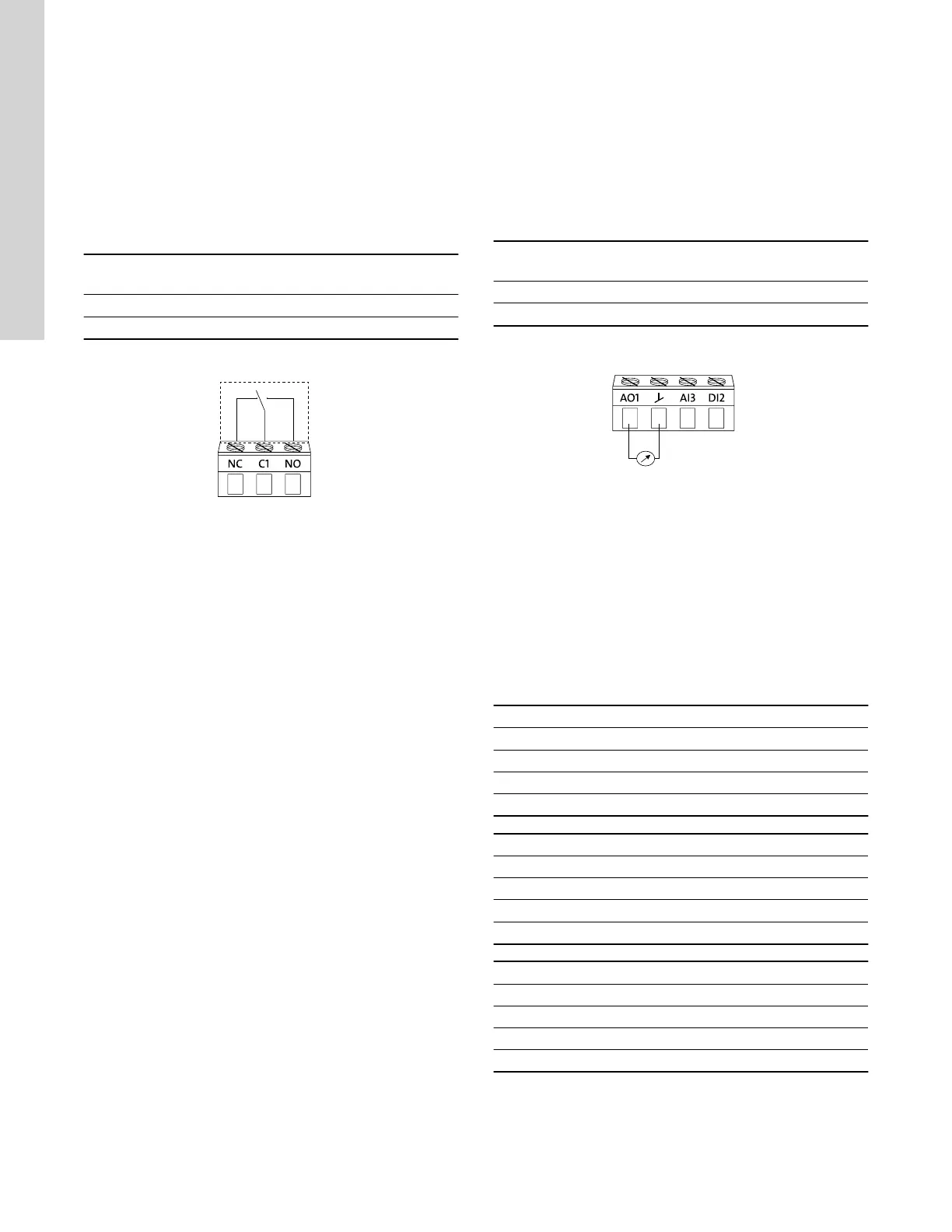
10.14 Analog output
The inputs and outputs available depend on the functional module
fitted in the motor.
Functional module
Analog output
(Terminals AO, GND)
FM310 •
FM311 •
Wiring example:
TM083185
Analog output, 0/4-20 mA, 0-10 V
The analog output enables external control systems to read specific
operating data.
To set the analog output, make the following settings.
Output signal
Possible signal types:
• 0-10 V
• 0-20 mA
• 4-20 mA.
Function of analog output
Actual speed
0 % 100 %
0 V 10 V
0 mA 20 mA
4 mA 20 mA
Sensor value
Minimum Maximum
0 V 10 V
0 mA 20 mA
4 mA 20 mA
Resulting setpoint
0 % 100 %
0 V 10 V
0 mA 20 mA
4 mA 20 mA
44
English (US)

 Loading...


