Motor load
0 % 100 %
0 V 10 V
0 mA 20 mA
4 mA 20 mA
Motor current
0 % 100 % 200 %
0 V 5 V 10 V
0 mA 10 mA 20 mA
4 mA 12 mA 20 mA
Limit-exceeded function
Output not active Output active
0 V 10 V
0 mA 20 mA
4 mA 20 mA
10.15 Controller (Controller settings)
The pumps have a factory default setting of gain (K
p
) and integral
time (T
i
).
However, if the factory setting is not the optimum setting, you can
change the gain and the integral time:
• Set the gain within the range from 0.1 to 20.
• Set the integral-action time within the range from 0.1 to 3600
seconds. If you select 3600 seconds, the controller functions as
a PI controller.
Furthermore, you can set the controller to inverse control.
This means that if you increase the setpoint, the speed is reduced.
In the case of inverse control, you must set the gain within the
range from -0.1 to -20.
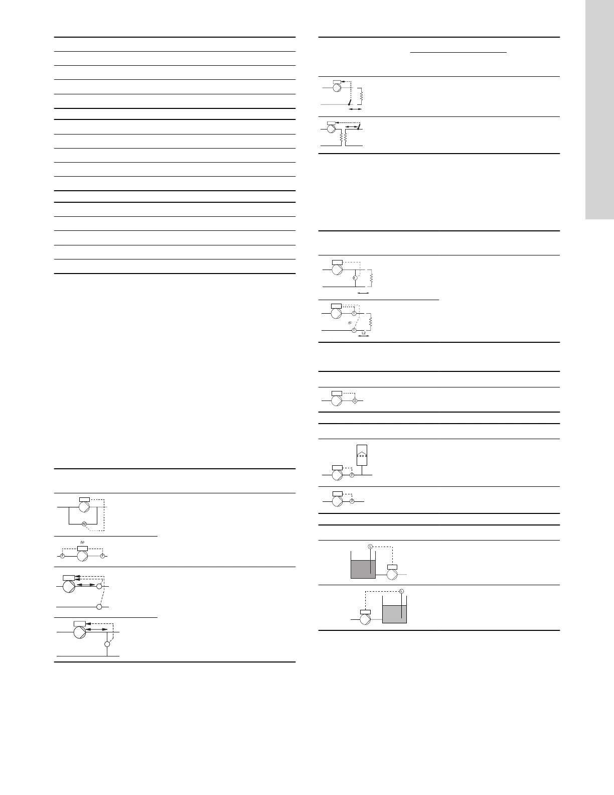
Guidelines for setting of PI controller
The tables below show the recommended controller settings:
Constant differential
pressure
K
p
T
i
0.5 0.5
0.5
L1 < 16 ft: 0.5
L1 > 16 ft: 3
L1 > 32 ft: 5
L1: Distance in feet between the pump and the sensor.
Constant temperature
K
p
T
i
Heating
system
Cooling
system
0.5 -0.5
10 +
1.524×L2
0.5 -0.5
30 +
1.524×L2
10)
In heating systems, an increase in pump performance results in a rise in
temperature at the sensor.
11)
In cooling systems, an increase in pump performance results in a drop in
temperature at the sensor.
L2: Distance in feet between the heat exchanger and the sensor.
Constant differential
temperature
K
p
T
i
-0.5
10 +
1.524×L2
L2: Distance in feet between the heat exchanger and the sensor.
Constant flow rate
K
p
T
i
0.5 0.5
Constant pressure
K
p
T
i
0.5 0.5
0.5 0.5
Constant level
K
p
T
i
-10 0
10 0
General rules of thumb:
If the controller is too slow-reacting, increase the gain.
If the controller is hunting or unstable, dampen the system by
reducing the gain or increasing the integral time.
Factory setting
See the section on factory settings.
Related information
10.57 Factory settings for Grundfos GO
45
English (US)

 Loading...


