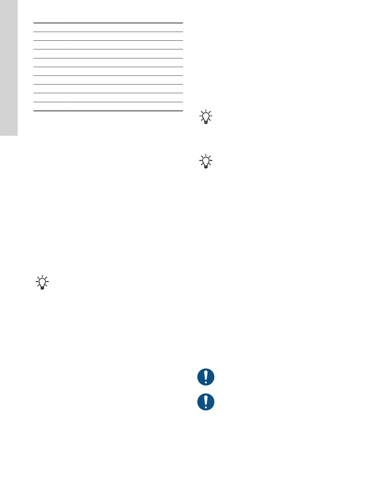
Pos. Description
Y Speed
X Time
1 Fixed maximum
2 User-set maximum
3 User-set minimum
4 Fixed initial ramp
5 Fixed final ramp
6 Ramp time up
7 Ramp time down
10.27 Direction of rotation
Use this function to select the desired direction of motor rotation
when looking at the motor shaft end from the drive side.
• clockwise
• counterclockwise
The displayed direction of rotation applies when the digital inputs for
reversing the rotation are not active.
10.28 Skip band
Use this function to select a skip band within the range from user-
set minimum speed to user-set maximum speed if continuous
operation is not required. The upper and lower speeds are stated in
percentage of rated speed.
The purpose of the skip band is to avoid certain speeds which may
cause noise or vibrations. If no skip band is required, select -.
10.29 Standstill heating
Use this function to avoid condensation in humid environments.
When you set the function to Active and the product is in operating
mode Stop, a low AC voltage is applied to the motor windings. The
voltage is not high enough to make the motor rotate, but ensures
that sufficient heat is generated to avoid condensation in the
product, including the electronic parts in the drive.
Remember to remove the drain plugs and fit a cover over
the product.
10.30 Alarm handling
This setting determines how the pump must react in case of a
sensor failure.
Alarm or warning types:
• Warning
A warning. There is no change in the operating mode.
• Stop
The pump stops.
• Min.
The pump reduces the speed to minimum.
• Max.
The pump increases the speed to maximum.
• User defined speed
The pump runs at the speed set by the user.
Affected inputs:
• Analog input 1
• Analog input 2
• Analog input 3
• Built-in Grundfos sensor
• Pt100/1000 input 1
• Pt100/1000 input 2
• Liqtec input.
10.31
Motor bearing monitoring
Use this function to select whether or not you want to monitor the
motor bearings.
You can make the following settings:
• Active
• Not active
When the function is set to Active, a counter in the controller starts
counting the running hours of the bearings. The running hours are
calculated on the basis of the motor speed. When a predefined limit
is reached, a warning indicates that the bearings must be replaced
or relubricated.
If you change the function to Not active, the counter
continues to count. However, no warning is given when it
is time to replace the bearings. If you change the function
to Active again, the accumulated running hours are used
to recalculate the replacement time.
10.32 Service intervals
Motor bearing monitoring must be activated in order for
the motor to indicate that the bearings must be replaced
or relubricated. See the section on motor bearing
monitoring.
For motors of 10 HP (7.5 kW) and below, it is not possible to
relubricate the bearings.
10.32.1
Time to next service (Motor bearing service)
This display shows when to replace the motor bearings. The
controller monitors the operating pattern of the motor and calculates
the period between bearing replacements.
Displayable values:
• in 2 years
• in 1 year
• in 6 months
• in 3 months
• in 1 month
• in 1 week
• Now!
10.32.2
Bearing replacements
The display shows the number of bearing replacements made
during the lifetime of the motor.
10.32.3
Bearings replaced (Motor bearing maintenance)
When the bearing monitoring function is active, a warning is given
when the motor bearings must be replaced.
1. When you have replaced the motor bearings, press Bearings
replaced.
10.32.4
Bearings relubricated
When the bearing monitoring function is active, a warning is given
when the motor bearings must be relubricated.
Bearings can be relubricated 5 times before they must be
replaced.
The amount of grease can be found on the bearing
nameplate on the motor.
1. When you have relubricated the bearings, press Bearings
relubricated.
10.33
Communication
Use this function to set the communication of the product, both
wired and wireless communication. The product contains built-in
fieldbus protocols on the AYB terminals (RS-485).
52
English (US)

 Loading...


