中文 (CN)
282
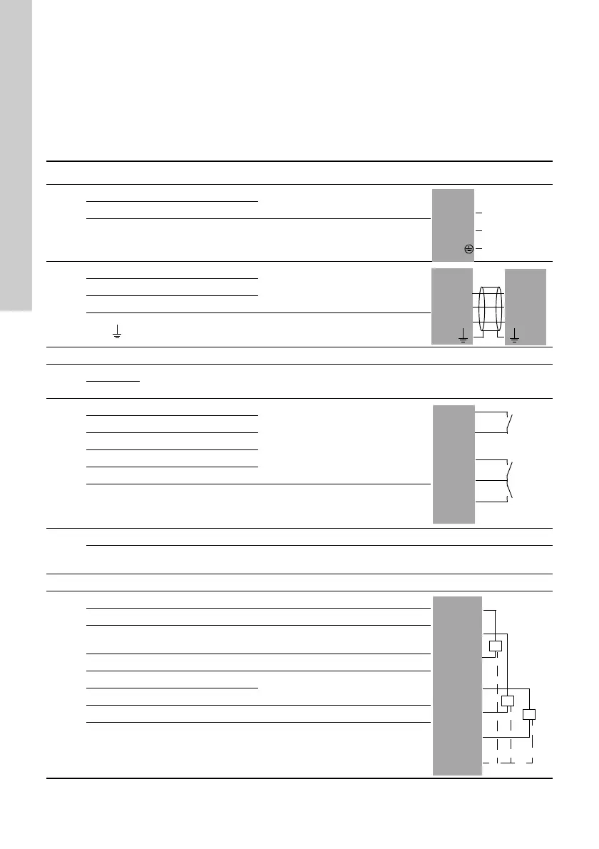
10. 输入输出概览表
DI: 数字量输入
DO: 数字输出
AI: 模拟输入
NC: 常闭触点
NO: 常开触点
C: 共用。
位置号,见图17。
组 端子 描述 数据 接线图
1
L 连接相位导线
1 x 100-240 VAC ± 10 %, 50/60 Hz
N 连接中性导线
PE 保护性地线接头
2
A1 RS-485 A
GENIbus
利用电缆夹固定屏蔽层。
Y1 RS-485 GND
B1 RS-485 B
功能性接地
3 连接外部 fieldbus 总线,参见 CIM 模块的安装与操作指导。
4
0 V
连接电池 备用电池
+12 VDC
5
10 DI1
数字量输入
11 GND
12 DI2
13 GND
14 DI3
所有端子 (除供电电源外)连接的电压不得高于 16 V
rms
及 22.6 V
peak
或
35 VDC。
6
Ethernet RJ45
连接到以太网上的所有外部计算设备均必须服从 IEC 60950 和 UL 60950
标准的规定。
7 GENIbus 服务接口
8
47 +24 V 传感器直流电源。 短路保护 30 mA
50 +24 V 传感器直流电源。 短路保护 30 mA
51 AI1
模拟信号的输入,
0-20/4-20 mA 或 0-10 V
53 +24 V 传感器直流电源。 短路保护 30 mA
54 AI2
模拟信号的输入,
0-20/4-20 mA 或 0-10 V
57 AI3
58 GND*
所有端子 (除供电电源外)连接的电压不得高于 16 V
rms
及 22.6 V
peak
或
35 VDC。
 Loading...