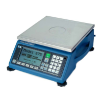
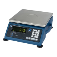
10 Model 675 User Instructions
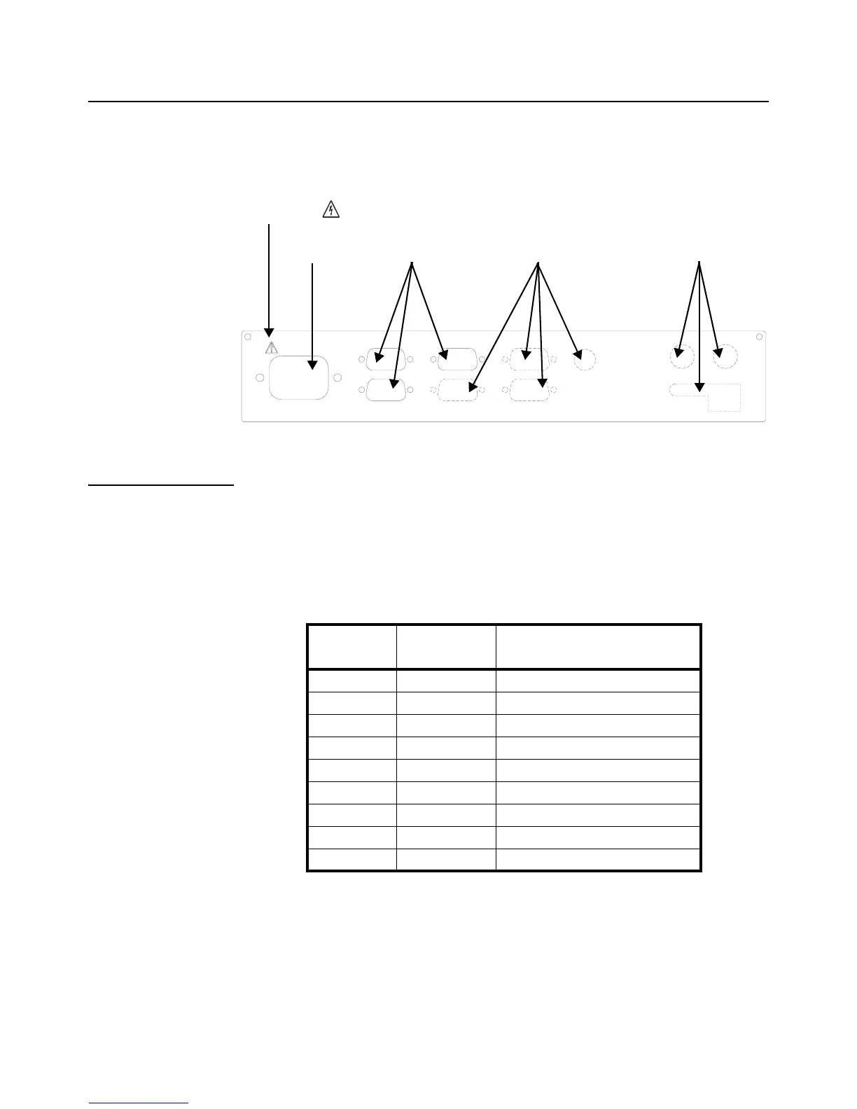
1.11 Rear Panel
The Model 675 comes standard with 2 communication ports, which use Male DB-9
connectors. A remote base can also be connected to the SCALE 2 Female DB-9
connector. The positions that are shown with dotted lines are available for options such
as scale 3 and 4, Ethernet, communication ports and setpoints.
NOTE: The means CAUTION. Disconnect power before servicing
1.11.1 Scale 2 Connections (Remote Scale)
If a 4-wire load cell cable is being used, jumpers will need to be installed between sense
and excitation. The jumpers will be installed on the DB9 connector being installed on
the load cell cable. The intention of pins 8 and 9 on the DB9 are to connect the sense
and excitation in 4 wire load cell applications without having to solder two wires in one
hole. Refer to Table 1.3 for scale 2 pin out connections.
Table 1.3 Scale 2 DB9 Connector Pin Out
Power Standard Options Options
ETHERNET
AUX 3
AUX 2
PS/2
COM 4
COM 3
675 PRECISION COUNTING SCALE
AUX 1
90-250VAC
50-60Hz 0.8A
SCALE 2COM 1
COM 2
WARNING
DB9 pin
designation
Connection Load Cell Cable
1 + Signal 4 or 6 wire
2 - Signal 4 or 6 wire
3 + Sense 4 wire (connect a wire jumper to pin 8)
4 - Sense 4 wire (connect a wire jumper to pin 9)
5 - Excitation 4 or 6 wire
6 + Excitation 4 or 6 wire
7 Chassis Ground 4 or 6 wire
8 + Excitation 4 wire (connect a wire jumper to pin 3)
9 - Excitation 4 wire (connect a wire jumper to pin 4)