Model 675 User Instructions 11
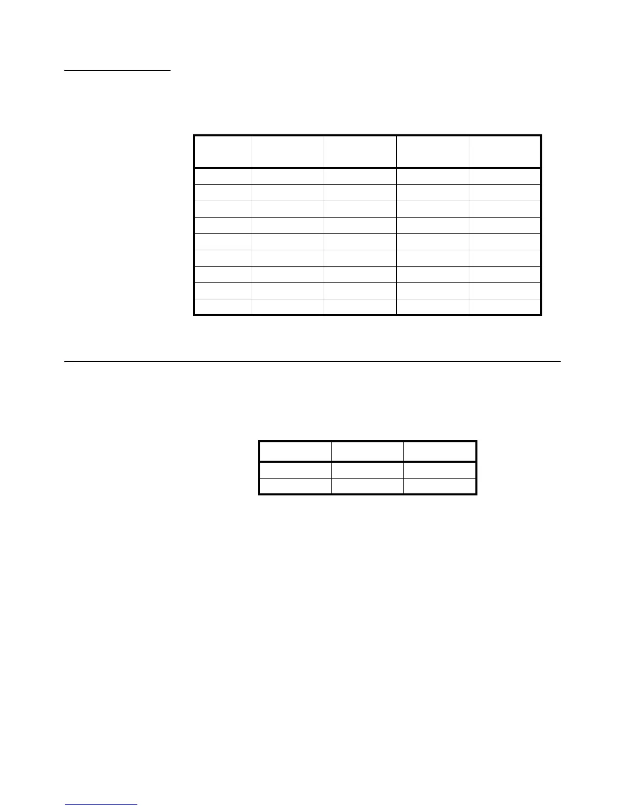
1.11.2 Communication Port Connections
Comm port 1 and 2 are standard on the Model 675. Comm port 3 and Comm port 4 are
optional. Refer to Table 4 for communication port pin outs.
Table 1.4 Comm Port 1 - 4 Pin Out
1.12 Remote Key Connections
The Model 675 allows for two remote key inputs. The inputs can be used for invoking
a macro to perform tasks such as zero, print, tare etc. See the chart below for comm
port and pin assignment.
Table 1.5 Remote Key
DB9 pin Comm 1 Comm 2
Comm 3
(optional)
Comm 4
(optional)
1 No connection TTL No connection No connection
2 RXD RXD RXD RXD
3 TXD TXD TXD TXD
4 + 5 V + 5V + 5V + 5V
5 ISO Ground Ground Ground Ground
6 Ground Ground Ground Ground
7 RTS RTS No connection No connection
8 CTS CTS CTS No connection
9 Remote Key 1 Remote Key 2 No connection No connection
Remote Key Port Pins
1 Comm 1 6 and 9
2 Comm 2 6 and 9