4. Assembly and Installation
26 PNEG-1156ETL Design III Series Grain Stir-Ator CSA
Frame Rails
1. To assemble the Design III Stir-Ator, place the frame rails on two (2) sawhorses and remove the
two (2) 5/16" bolts holding the frame rails together, spacing them approximately 8".
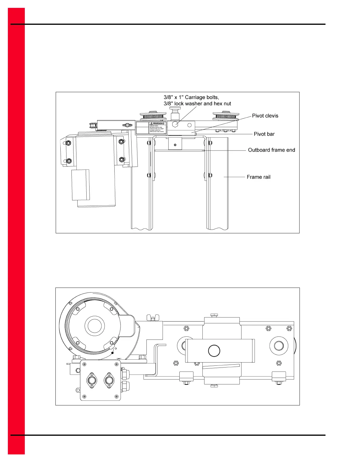
2. For Double and Triple Auger Units: Bolt outboard frame end and track unit assembly to the frame
rails using six (6) 3/8" x 1" carriage bolts, 3/8" lock washers and hex nuts. Tighten with the socket
head on an impact wrench and use a hand wrench where necessary. (See Figure 4L.)
Figure 4L Double and Triple Auger
NOTE: Locate bolt heads to inside of frame rails.
3. The outboard frame end has two (2) pivot positions. One is for the heavier 2 HP motors, the other is
used for all 1-1/2 HP and the light modeled 2 HP motors. Use the position of the pivot bar to
determine HP. If the pivot bar is on bottom, it is set for 1-1/2 HP. (See Figure 4M.)
Figure 4M 2 HP
NOTE: Frame rails are removed for clarity.
 Loading...