4. Assembly and Installation
PNEG-1156ETL Design III Series Grain Stir-Ator CSA 33
Swing Arm
1. Carefully remove the zip tie that are holding cord to swing arm.
Junction Box
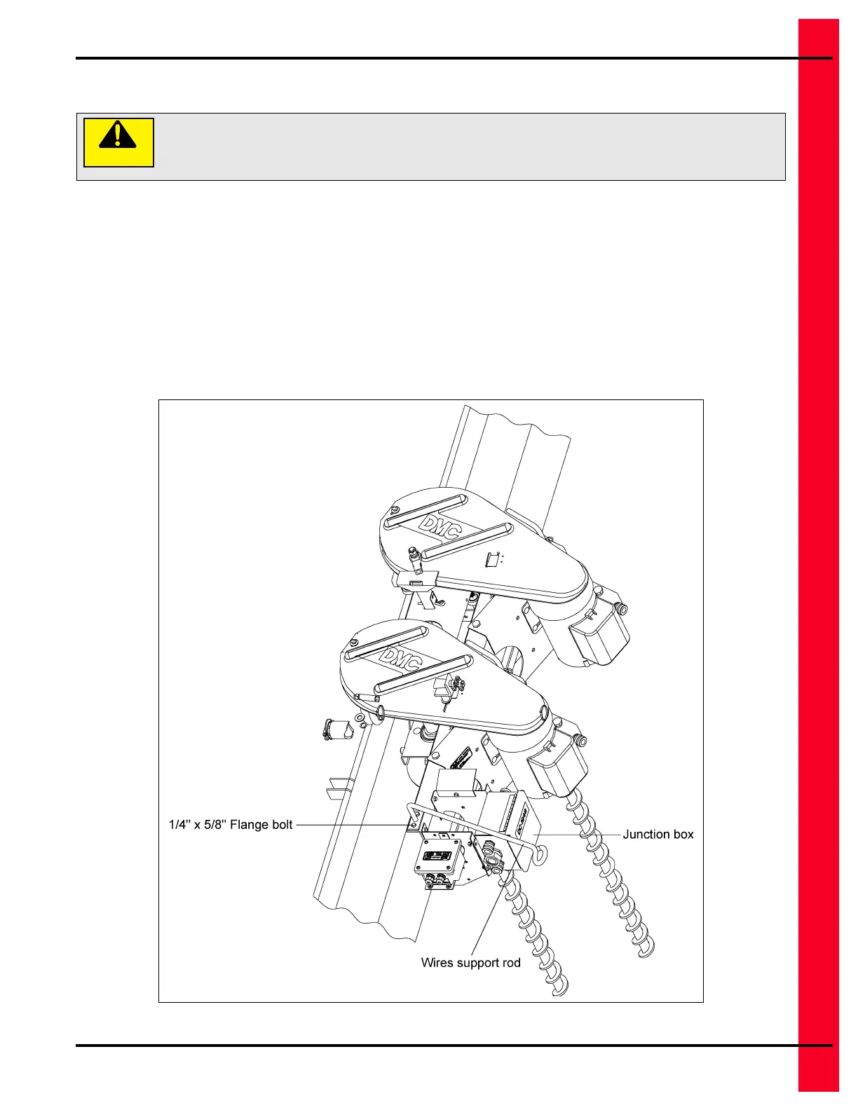
1. Bolt trolley wire support rod to the top of the angle support with two (2) 1/4" x 5/8" flange bolt and
1/4" hex flanged lock nuts. After removing the screw from the junction box cover, feed electrical wires
through the end loop of the wire support and into the junction box. Connect ends to terminal wires
through the end loop of the wire support and into the junction box. Connect ends to the terminal strip
and the solid state electronic tilt switch electrical wire using wire connectors. (See Wiring Diagrams
on Pages 79-82 or See Figure 4Z.)
Figure 4Z
Swing arm is spring loaded. Extreme care must be exercised when cutting the
shipping zip ties loose to avoid possibility of personal or bodily injury, as arm will
snap back when freed.
 Loading...