4. Assembly and Installation
34 PNEG-1156ETL Design III Series Grain Stir-Ator CSA
2. After making electrical connections, replace cover screw. Secure electrical wires to wire support rod
using two (2) wire ties. Trim excess. (See Figure 4AA and Figure 4AB.)
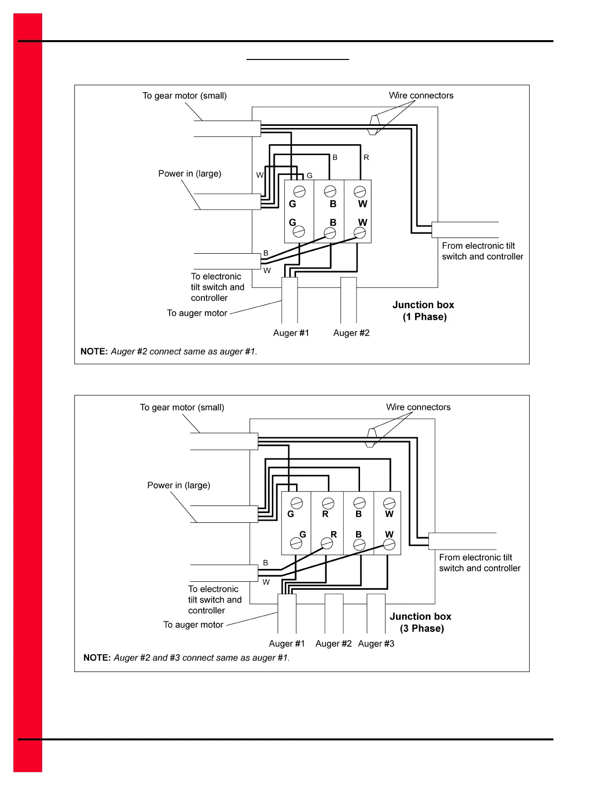
Figure 4AA Junction Box Wiring Diagram - 1 Phase
Figure 4AB Junction Box Wiring Diagram - 3 Phase
 Loading...