GST200 Intelligent Fire Alarm Control Panel
Installation and Operation Manual
The Intelligent Solution
Page 15
Fig. 4-2a
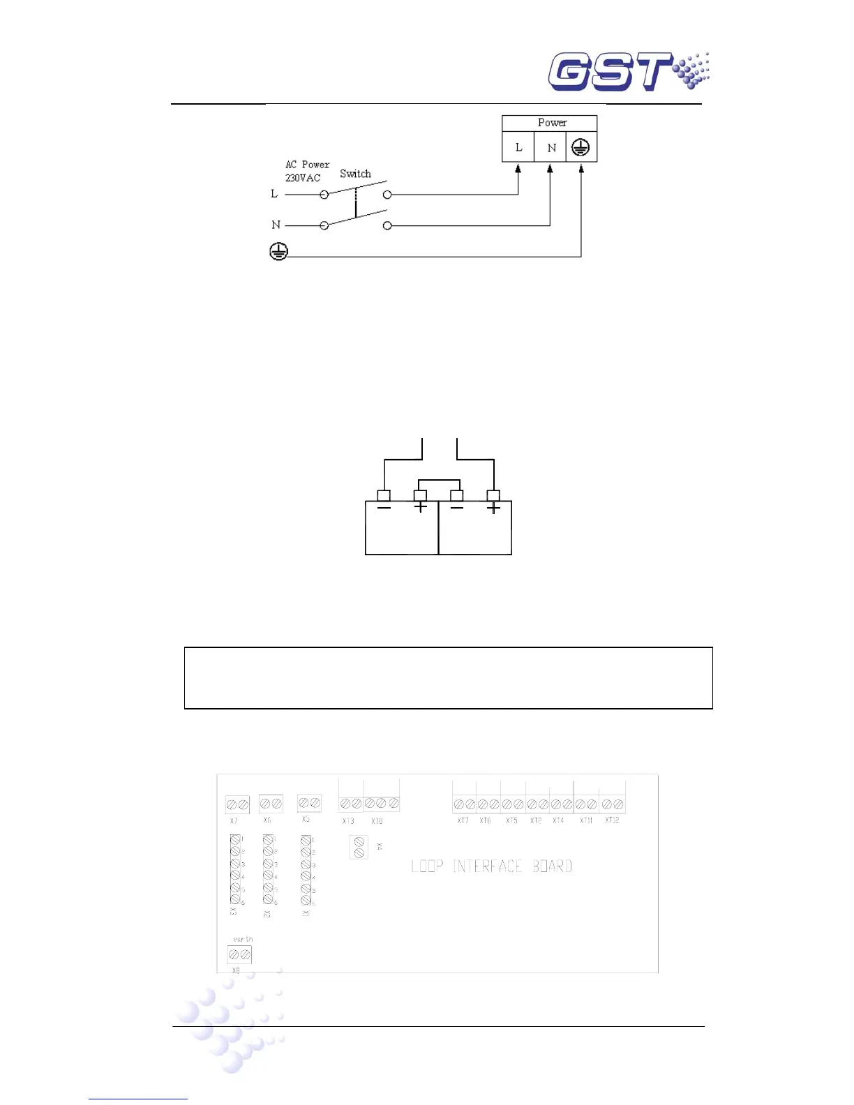
4.4.2 Connection of Batteries
Refer to the Standby Battery Calculations section for the size of the batteries required
for a particular installation.
Connect the batteries according to Fig. 4-2b and then connect with the battery terminal
P4.
P4(+)
P4(-)
Fig. 4-2b
Note: Do not make the final battery connections until the installation is complete.
4.4.3 Connection of Field Devices
Caution: Do not connect power to your device until you have completed all
input and output connections. Failure to do so may result in injury!
GST200 connects with field devices by loop interface board.
Terminals of loop interface board are shown in Fig. 4-3.
LOOP BUS
LOOP OUT
- +
RS - 485
NETWORK
B A
REPEATER
B A
- +
SOUNDER
CIRCUIT
POUTPUT
F.P.E
OUTPUT
LOOP IN
+ -
- +
FIRE
ALARM
OUTPUT
- +
FAULT OUTPUT
NO COM NC
CLASS
CHANGE
Fig. 4-3
 Loading...