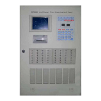
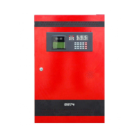
GST200 Intelligent Fire Alarm Control Panel
Installation and Operation Manual
The Intelligent Solution
Page I
CONTENTS
Installation Precautions............................................................................................. 1
Preface EN 54 Information......................................................................................... 2
Chapter 1 Product Introduction ................................................................................ 3
Chapter 2 Technical Specifications .......................................................................... 4
2.1 Operating Voltage ............................................................................................... 4
2.2 Standby Batteries................................................................................................ 4
2.3 Communication Loop Parameters ...................................................................... 4
2.3.1 RS-485 Communication Loop................................................................. 4
2.3.2 RS-232 Communication Loop................................................................. 4
2.4 Detecting Loop Parameters ................................................................................ 5
2.5 Output Loop Parameters .................................................................................... 5
2.5.1 FIRE ALARM OUTPUT (+, -) .................................................................. 5
1.1.1 F.P.E. OUTPUT (+, -) .............................................................................. 5
2.5.2 SOUNDER CIRCUIT OUTPUT (+, -) ...................................................... 5
2.5.3 FAULT OUTPUT (NC, COM, NO) ........................................................... 5
2.6 Dimensions ......................................................................................................... 5
Chapter 3 Structure and Configuration.................................................................... 6
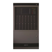
3.1 Appearance and Internal Structure ..................................................................... 6
3.1.1 Display Area............................................................................................ 7
3.1.2 Description of LEDs ................................................................................ 7
3.1.3 Description of Keys ................................................................................. 8
3.1.4 Zone Indication and Manual Interventional Panel (ZCP)......................... 9
3.2 Configuration .................................................................................................... 10
3.2.1 Standard Configuration ......................................................................... 10
1.1.2 Optional Units ....................................................................................... 10
3.3 Periphery Devices..............................................................................................11
3.3.1 A Series of Intelligent Fire Detectors......................................................11
3.3.2 Modules .................................................................................................11
3.3.3 Loop Isolator ......................................................................................... 12
3.3.4 Manual Call Points................................................................................ 12
3.3.5 Sounder Strobes ................................................................................... 12
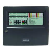
3.3.6 GST852RP Repeater Panel.................................................................. 12
3.4 GstDef2.0 Defining Tool.................................................................................... 12
Chapter 4 Installation............................................................................................... 13
4.1 Configuration Inspection ................................................................................... 13
4.2 Installing the Cabinet ........................................................................................ 13
4.3 Start-up Check .................................................................................................. 14
4.4 Connections of Field Devices ........................................................................... 14
4.4.1 Connection of AC Power....................................................................... 14
4.4.2 Connection of Batteries......................................................................... 15
4.4.3 Connection of Field Devices ................................................................. 15
4.5 Connection Inspection and Device Registration ............................................... 18
4.5.1 Connection Inspection .......................................................................... 18
4.5.2 Device Registration............................................................................... 19
4.6 Device Definition............................................................................................... 19