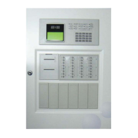
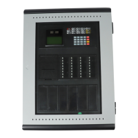
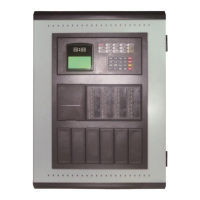
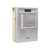
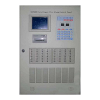
GST200 Intelligent Fire Alarm Control Panel
Installation and Operation Manual
The Intelligent Solution
Page 4
Chapter 2 Technical Specifications
2.1 Operating Voltage
Input Voltage: 230VAC
+10%
-15%
Frequency: 50Hz
Input Current: 0.5A
Fuse: 2A delay
Recommended Wiring: 1.5mm
2
or above shield cable, complying with local
installation code.
2.2 Standby Batteries
Maximum Charge Current: 1.1A±0.1A
Maximum Charge Voltage: 27.3V±0.3V
Type: Sealed lead acid batteries
Maximum Charge Capacity: 2 12V/17Ah batteries
Recommended manufacturer and model of battery: Yuasa NP17-12I
Recommended Wiring (subject to local installation codes):
GST FireCable ® 2E/1.5 2 core and Earth 1.5mm
2
CSA
Pirelli Cable Limited FP200 FLEX 2 core and Earth 1.5mm
2
CSA
2.3 Communication Loop Parameters
2.3.1 RS-485 Communication Loop
NETWORK (A, B): Communication cable for connecting with up to 32 network
FACPs.
REPEATER (A, B): Communication cable for connecting with up to 10 repeater
panels.
Recommended Wiring (subject to local installation codes):
GST FireCable ® 2E/1.0 2 core and Earth 1mm
2
CSA
Pirelli Cable Limited FP200 FLEX 2 core and Earth 1mm
2
CSA
Recommended Cable Length ≤1000m
2.3.2 RS-232 Communication Loop
RS232 communication loop is connected with a PC for running GstGMC2.0 Graphic
Monitor Center (GMC) system PC through DB9 port.
Recommended Wiring: Standard RS-232 interface. The 2
nd
pin (for sending data), the
3
rd
pin (for receiving data), and the 5
th
pin (ground) are connected with PC through
three-core shield cable (Note: Wire length should be less than 15m; shield layer
and computer’s enclosure should be earthed).