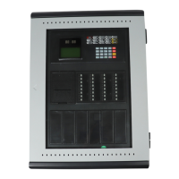
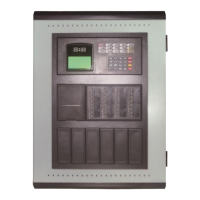
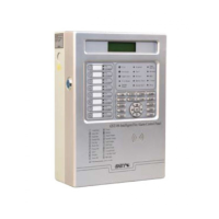
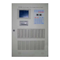
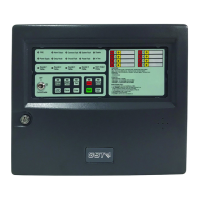
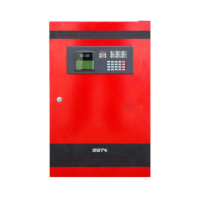
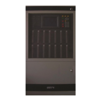
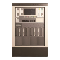
GST200 Intelligent Fire Alarm Control Panel
Installation and Operation Manual
The Intelligent Solution
Page 23
Keypad fault: The panel reports keypad fault if its keypad circuit is in fault:
¾ It lights the COMMON FAULT and SYSTEM FAULT LED.
¾ The LCD displays “Key fault”.
¾ The panel generates continuous alarm sound.
¾ Fault relay outputs.
¾ The keypad cannot be used.
¾ The panel can monitor fire alarm.
¾ The panel can reset automatically after the fault is removed.
Field device fault: If there is trouble with one of the field devices, the panel reports
fault with it, and
¾ The panel lights the COMMON FAULT LED.
¾ The corresponding ZCP LED flashes.
¾ The panel generates fault sound.
¾ Fault relay outputs.
¾ The LCD displays the fault message. The fault screen is as in Fig. 5-5 in zone
display mode, and as in Fig. 5-6 in loop display mode.
Fig. 5-5
001 0f 002 FAULT10:18
Zone:003-floor3
Office3
¾ 001 0f 002 FAULT10: 18 // There are two zones reporting fault, and this is the
first fault message.
¾ Zone:003-floor3 // The number description of the zone with fault message.
¾ Office3 // Description of the device with the fault.
001 0f 004FAULT10:18
Zone:003-011Optical
Fig. 5-6


 To Next Page