4-40
SFP+ port—SFP+ fiber transceiver module and optical fiber or SFP+ cable. For the available
transceiver models and cables, see ports in Hardware Information and Specifications.
If the IRF member switches are far away from one another, use SFP/SFP+ transceiver modules and
optical fibers. If the IRF member switches are all in one equipment room, use twisted pair cables or
SFP/SFP+ cables.
As a best practice, use ring topology to connect the switches. The following describes cabling
schemes in ring topology by using SFP+ cables and SFP+ transceiver modules and fibers to connect
four switches.
Connecting the IRF member switches in one rack
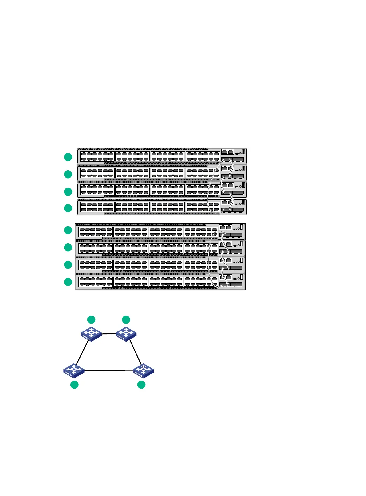
Use SFP+ cables to connect the IRF member switches in a rack as shown in Figure 4-4. The
switches in the ring topology (see Figure 4-5) are in the same order as connected in the rack.
Figure 4-4 Connecting the switches in one rack
Figure 4-5 IRF fabric topology
Connecting the IRF member switches in a ToR solution
You can install IRF member switches in different racks side by side to deploy a top of rack (ToR)
solution.
Figure 4-6 shows an example for connecting 4 top of rack IRF member switches by using SFP+
transceiver modules and optical fibers. The topology is the same as Figure 4-5.

 Loading...


