4-41
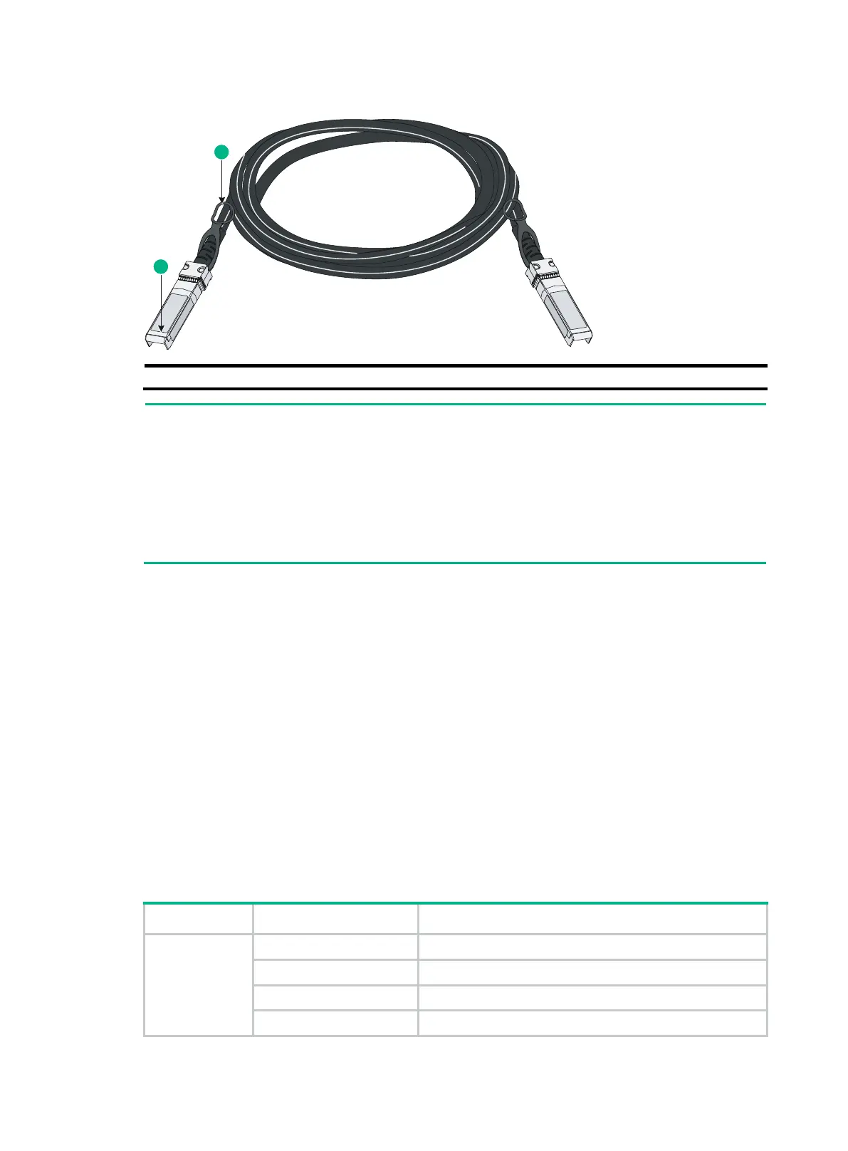
Figure4-1 SFP+ cable
As a best practice, use only H3C SFP/SFP+ transceiver modules and SFP+ cables
ports.
The H3C SFP/SFP+ transceiver modules and SFP+ cables available for the SFP+ ports are
subject to change over time. For the most recent list of SFP/SFP+ transceiver modules and
SFP+ cables, contact your H3C Support or marketing staff.
For the specifications of H3C SFP/SFP+ transceiver modules and SFP+ cables, see H3C
Transceiver Modules User Guide.
Combo interface
The S5560S-28F-EI, S5560S-28S-EI, S5560S-28P-EI, S5130S-28S-HI, and S5130S-28C-HI
switches each provide eight combo interfaces on the front panel. The S5560S-28S-PWR-EI,
S5130S-28S-PWR-HI, and S5130S-28C-PWR-HI switches each provide four combo interfaces on
the front panel. The S5560S-52F-EI, S5130S-52C-HI, and S5130S-52C-PWR-HI switches each
provide two combo interfaces on the front panel. A combo interface contains an SFP port and a
10/100/1000BASE-T autosensing Ethernet port. Only one of these two ports can operate at a time.
LEDs
System status LED
The system status LED shows the operating state of the switch.
Table4-9 System status LED description
LED mark Status Description
SYS
Steady green The switch is operating correctly.
Flashing green (1 Hz) The switch is performing power-on self test (POST).
Steady red The switch has failed the POST or is faulty.
Off The switch is powered off.

 Loading...


