20
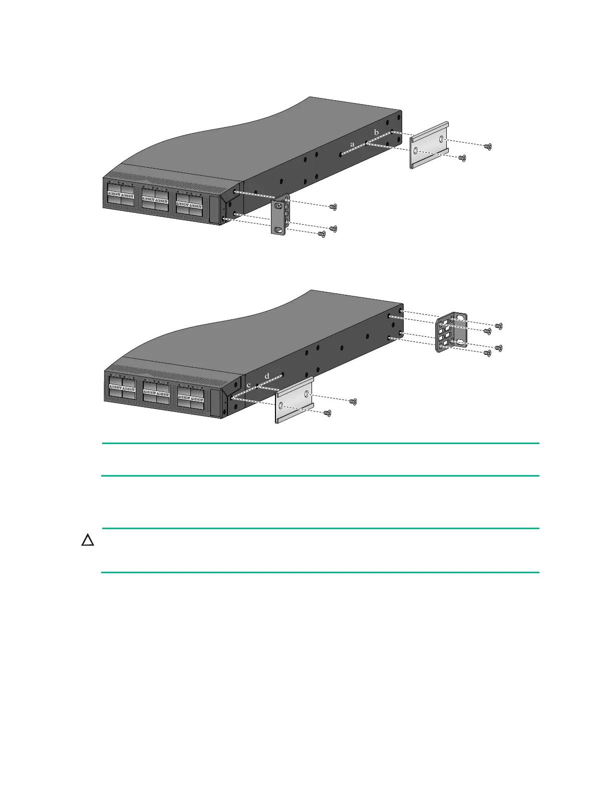
Figure 32 Attaching the mounting brackets and chassis rails to the S9850-32H switch
(port-side mounting position for the mounting brackets)
Figure 33 Attaching the mounting brackets and chassis rails to the S9850-32H switch (power
module-side mounting position for the mounting brackets)
NOTE:
Secure the mounting brackets and chassis rails to both sides of the chassis in the same way.
Connecting the grounding cable to the chassis
CAUTION:
If you use one of these grounding points, you must connect the grounding cable to the grounding
point before you mount the switch in the rack.
For the S6850-56HF, S6850-2C and S9850-32H switches, the primary grounding point and auxiliary
grounding point are located on the left panel. For the S9850-4C switch, the primary grounding point
and auxiliary grounding point 1 are located on the left panel, and auxiliary grounding point 2 is
located on the rear panel.
As a best practice, use the primary grounding point or auxiliary grounding point on the left panel. The
grounding cable and grounding screw that come with the switch are suitable only for these two
grounding points. To use auxiliary grounding point 2 on the S9850-4C switch, prepare a grounding
cable with a ring terminal at each end yourself or purchase the grounding cable (code 0404A0CP)
from H3C.
The procedure for connecting the grounding cable to the grounding points on the left panel is the
same. This section uses the primary grounding point on the S6850-56HF switch as an example.

 Loading...


