21
To connect the grounding cable to a grounding point on the left panel:
1. Choose a grounding point as required.
When you install the mounting brackets at the port-side mounting position, choose the auxiliary
grounding point. When you install the mounting brackets at the power module-side mounting
position, choose the primary grounding point.
This example uses the primary grounding point.
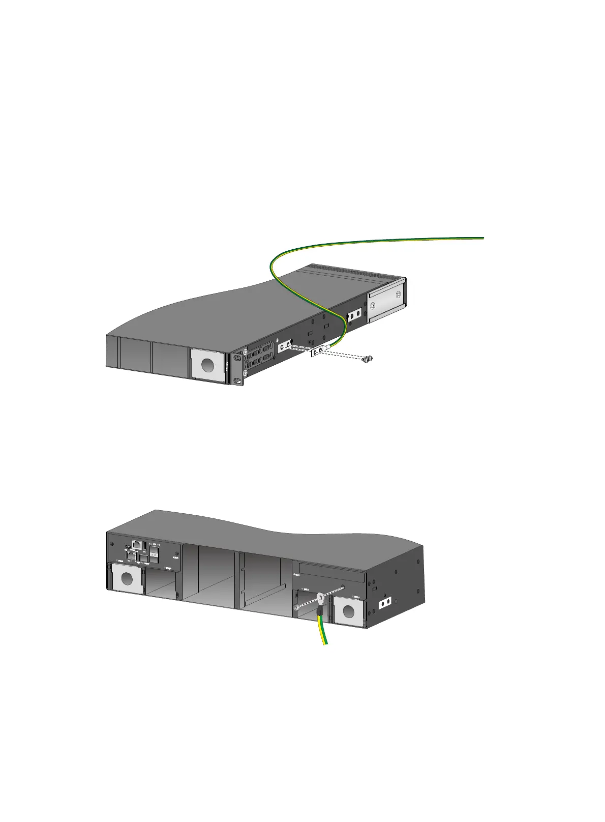
2. Unpack the grounding cable and grounding screws.
3. Use the two grounding screws to attach the two-hole grounding lug of the grounding cable to
the grounding holes at the grounding point (recommended torque: 20 kgf-cm). Use a
screwdriver to tighten the screws. See Figure 34.
Figure 34
Attaching the grounding cable to the primary grounding point on the S6850-56HF
switch
To connect the grounding cable to auxiliary grounding point 2 on the S9850-4C:
1. Remove the grounding screw from auxiliary grounding point 2.
2. Use the grounding screw to attach the ring terminal of the user-supplied grounding cable to the
grounding hole at the grounding point. Use a screwdriver to fasten the screw (recommended
torque: 20 kgf-cm). See Figure 35.
Figure 35
Attaching the grounding cable to auxiliary grounding point 2 on the S9850-4C
switch
Attaching the slide rails to the rack
The procedure is the same for attaching 1U and 2U slide rails to the rack. This section uses the 1U
slide rails as an example.
To attach the slide rails to the rack:

 Loading...


