71
SFP+ port
The LSWM124XG2Q, LSWM124XG2QFC, and LSWM124XG2QL interface modules each provide
24 SFP+ ports. The SFP+ ports support the following transceiver modules and cables:
• 10-GE SFP+ transceiver modules in Table 30.
• 10-GE SFP
+ copper cables in Table 31.
• 10-GE SFP
+ fiber cables in Table 32.
• GE SFP
transceiver modules in Table 17.
NOTE:
When a GE SFP module is installed in an SFP+ port on the LSWM124XG2QL interface card, the
SFP+ port does not support rate and duplex autonegotiation. You must configure the speed 1000
and duplex full commands on both ends.
LEDs
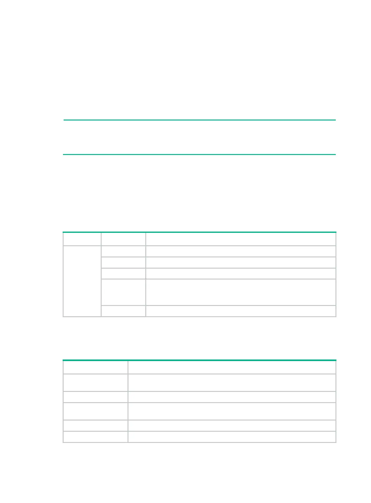
System status LED
The system status LED shows the operating status of the switch.
Table 33 System status LED description
LED mark Status Description
SYS
Steady green The switch is operating correctly.
Flashing green The switch is performing power-on self test (POST).
Steady red The system has failed to pass POST or has problems such as fan failure.
Flashing blue
(3 Hz)
Helps you to locate the switch.
To locate the switch in the rack, execute the
locator blink
blink-time
command. The LED then flashes blue at 3 Hz.
Off The switch is powered off or has failed to start up.
QSFP28 port LED
Table 34 QSFP28 port LED description
LED status Description
Steady green
A transceiver module or cable has been correctly installed. The port has a link and
is operating at 100 Gbps.
Flashing green The port is sending or receiving data at 100 Gbps.
Steady yellow
A transceiver module or cable has been correctly installed. The port has a link and
is operating at 10 Gbps, 25 Gbps, or 40 Gbps.
Flashing yellow (3 Hz) The port is sending or receiving data at 10 Gbps, 25 Gbps, or 40 Gbps.
Off No transceiver module or cable has been installed or no link is present on the port.

 Loading...


