31
To install a power module:
1. Wear an ESD wrist strap and make sure it makes good skin contact and is reliably grounded.
2. Remove the filler panel, if any, from the target power module slot, as shown in Figure 50.
Figure 50 Remov
ing a filler panel
3. Unpack the power module and verify that the power module model is correct.
4. Correctly orient the power module with the words on the power module upward. Grasp the
handle of the power module with one hand and support its bottom with the other, and slide the
power module slowly along the guide rails into the slot.
The slot is foolproof. If you cannot insert the power module into the slot, re-orient the power
module rather than use excessive force to push it in.
Figure 51 Installing a power module (LSVM1AC650)
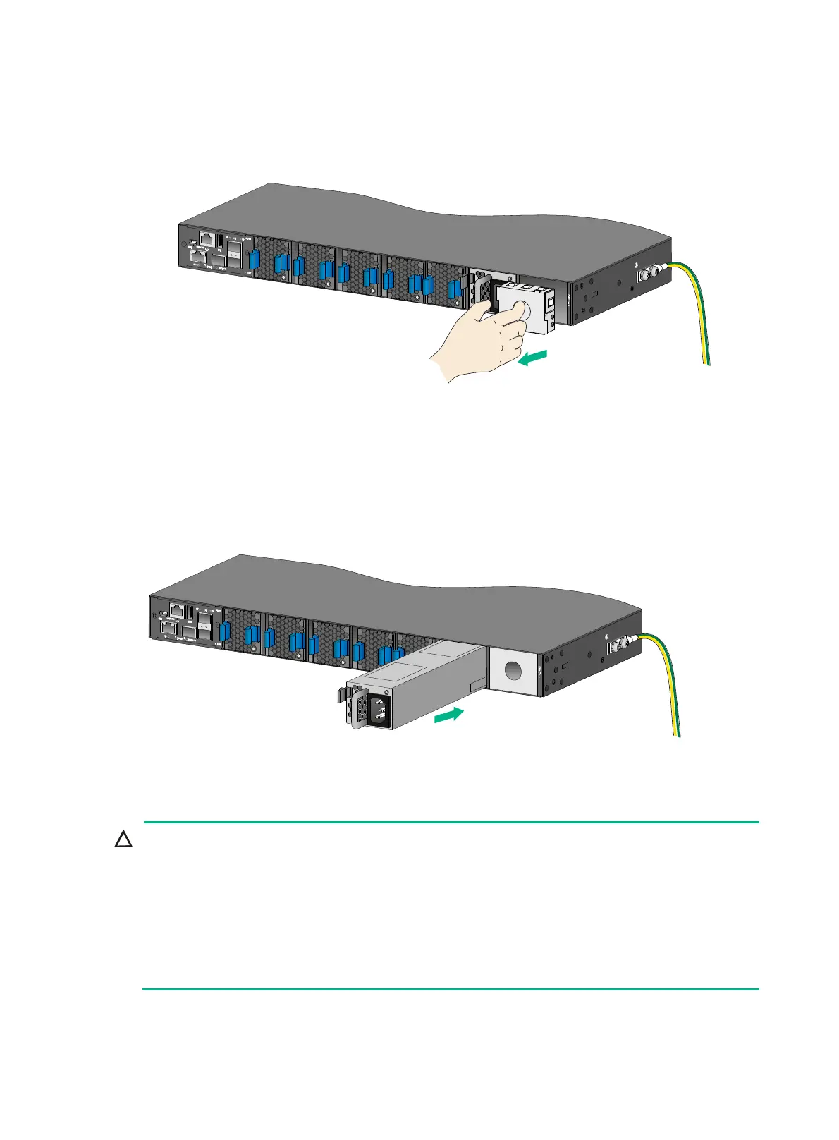
Removing a power module
CAUTION:
• When an S6850-56HF, S6850-2C, or S9850-32H switch has two power modules in 1+1
redundancy mode, removing one power module does not affect the operation of the switch.
When the switch has only one power module installed, removing the power module powers off
the switch.
• When an S9850-4C switch has power modules in 2+1 or 2+2 redundancy mode, removing one o
two power modules does not affect the operation of the switch. When the switch has only two
power modules installed, removing power modules powers off the switch or causes power
insufficiency.
The LSVM1AC650 and LSVM1DC650 removal procedure is the same on the S6850 and S9850
series switches. The figures in this section use the S6850-56HF switch as an example.

 Loading...


