57
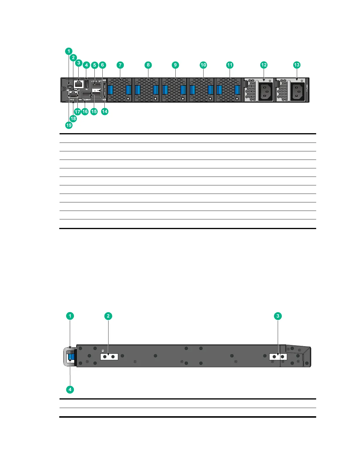
Figure 82 S9850-32H rear panel
(1) Mini USB console port (2) Copper management Ethernet port
(3) Serial console port (4) USB port
(5) SFP port (6) SFP port LED
(7) Fan tray 1 (8) Fan tray 2
(9) Fan tray 3 (10) Fan tray 4
(11) Fan tray 5 (12) Power module 1
(13) Power module 2 (14) Serial label pull tab
(15) Fiber management Ethernet port
(16) Fiber management Ethernet port LED (LINK/ACT)
(17) Copper management Ethernet port LED (ACT)
(18) System status LED (SYS) (19) Copper management Ethernet port LED (LINK)
The ESN serial number and MAC address of the S9850-32H switch can be found on the serial label
pull tab.
The S9850-32H switch comes with power module slot PWR1 empty and power module slot PWR2
installed with a filler panel. You can install one or two power modules for the switch as needed.
In Figure 82, two LSVM1A
C650 power modules are installed in the power module slots.
The S9850-32H switch comes with the five fan tray slots empty. You must install five fan trays of the
same model for the switch. In Figure 82,
five LSWM1FANSA fan trays are installed in the fan tray
slots.
Figure 83 S9850-32H left panel
(1) Fan tray handle (2) Primary grounding point
(3) Auxiliary grounding point (4) Power module handle

 Loading...


