11396-8000
June 1999
OPERATION
3.16 PART PROGRAM INPUT / OUTPUT
RS-232 DATA I NPUT / OUTPUT
Programs are sent or received through the first RS-232 port located on the rear control box pendant side. Note
that this is the top connector. All data sent or received is ASCII. In order to use this port, you will need to obtain
a cable and connectors with the following wiring:
pin #1 Shield Ground pin #2 TXD-Transmit Data
pin #3 RXD-Receive Data pin #4 RTS (optional)
pin #5 CTS (optional) pin #7 Signal Ground
Cables for the RS- 232 must be shielded
The following lists baud rate and the respective maximum cable length. This list assumes proper cable shield-
ing and no signal boost.
9,600 baud rate: 100feet (30m) RS-232
38,400 baud rate: 25 feet (8m) RS-232
115200 baud rate: 6 feet (2m) RS-232
It is possible to use RS-232 to RS-422 converters on each end of the cable to accomplish longer cables at up
to 115,200 baud. Proper twisted pair wire greatly improves reliability and increases maximum distance. A
pentium processor should be used for baud speed of 115,200.
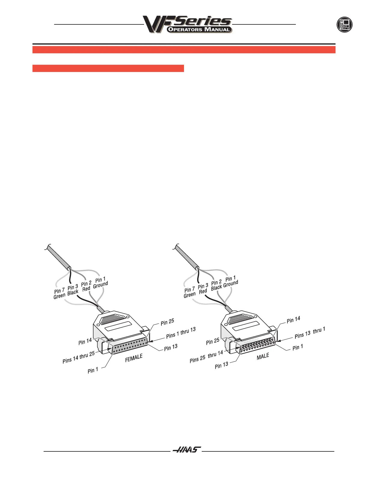
All other pins are optional and are not usually used. The RS-232 connector is a DB-25 and is wired as a DTE.
This means that we send data on the TXD wire and receive data on the RXD wire. If you do not understand this,
your dealer will be glad to help. The simplest connection would be to an IBM PC that can be done with a
standard cable made up of a DB-25 male on one end and a DB-25 female on the other. Pin 2 at one end is
wired to pin 3 at the other end, pin 3 to pin 2 and pin 7 is wired to pin 7.
 Loading...

